This thread has been locked.

If you have a related question, please click the "Ask a related question" button in the top right corner. The newly created question will be automatically linked to this question.

IO simulation SPI CLK ?

Other Parts Discussed in Thread: MSP430F149, MSP430F1611, MSP430F449

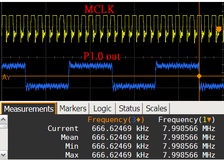
Will I want to use the MSP430F149 IO simulation SPI CLK frequency can  to 4MHZ?
If you can how to write code?

  • Your post is confusing. Perhaps you used a translator.  By IO simulation do you mean bit banging? i.e. making general IO to act as if it is SPI?

    If that is the case, you can find some general information here:

    http://en.wikipedia.org/wiki/Bit_banging

    As far as running bit banging at 4MHz, you'll obviously have to run the MCU at that speed or more.


    GL

  • this my msp430 code

    #include  <msp430x14x.h>

    void main(void)
    {
      WDTCTL = WDTPW + WDTHOLD;                 // Stop watchdog timer
      P1DIR |= 0x01;                                                   // Set P1.0 to output direction
       unsigned int j;
        WDTCTL = WDTPW +WDTHOLD;            // Stop Watchdog Timer
        BCSCTL1 = 0X00;                                        //將寄存器的內容清零
         //XT2震盪器開啟8MHz
         //LFTX1工作在低頻模式
         //ACLK的分頻因子為1
        do
        {
      // 清除OSCFault標誌
         IFG1 &= ~OFIFG;   
         for (j = 0xFF; j > 0; j--);               
        }
       while ((IFG1 & OFIFG));  
         
     //將寄存器的內容清零
        BCSCTL2 |= SELM_2 + SELS;                 // MCLK = SMCLK = XT2 =8Mhz(safe)
        P5DIR |= 0x70;                            // P5.6,5,4 outputs
      P5SEL |= 0x70;                            // P5.6,5,5 options
     
     
      for (;;)
      {
       // volatile unsigned int i;

        P1OUT ^= 0x01;                          // Toggle P1.0 using exclusive-OR

     
      }
    }

    BUT ,The  MSP430 of  P1.0  out  H-L  clk  only  650KHZ  , why????

  • That clarifies some of the code. 650kHz is around the default frequency of the MSp430 at startup, which might signify you did not successfully change the clock.

    Do you have a 8MHz crystal on XT2? A physical crystal?


    You set P5.6, 5.5 and 5.4 as outputs, use an oscilloscope to look the different clocks and verify that MCLK and SMCLK are in fact 8MHz.


    Just a general comment. The MSP430F149 is a rather antiquated device. The MSP430F1611 is somewhat superior, but why would you not take advantage of the

    MSP430F5xx family or some other devices? Maybe you just found it somewhere and that's all you have and your application doesn't need more.
    ANother comment is that the SPI modules requires that the clock divisor be at least 2. That means that 4MHz is the max with an 8MHz processor. This itself means that you need to provide 3.6V to the microcontroller. Other MSP430 derivatives have much higher frequencies at voltages lower than 3.6V.


    GL

  •  P5.6, 5.5 and 5.4 as outputs = MCLK and SMCLK are in fact 8MHz.

    but P1.0 output H-L = 650KHz

    I am use the MSP430F149 and MSP430F449  and MSP430F1611= The same result  .... why?

  •        Result

    DO you have test code? for MSP430F149 or 1611?

  • P1.0 Commonly has an LED. Do you have an LED connected on that pin? If so then it would not be possible to achieve the maximum frequency because LEDs have speed limitations for turn on/off and such. Perhaps if you provided schematics we could find the problem. The code is what I would call too simple to fail. You don't need to disable the watchdog twice. If you do have an LED on P1.0, test another pin. GL
  • my schematics:

                      MSP430F149
    //              ------------------------
    //         /|\  |                 XT2IN2|-
    //          |   |                              |    8MHz
    //           --|RST       XT2OUT|-
    //              |                              |
    //              |                      P1.0|-->oscilloscope(It is not the LED)

    //              |                       P5.4|-->MCLK = DCO Max   oscilloscope = 8Mhz
    //              |                       P5.5|-->SMCLK = XT2          oscilloscope = 8Mhz
    //              |                       P5.6|-->ACLK = 32kHz         oscilloscope = 32khz

    #include  <msp430x14x.h>

    void main(void)
    {
      WDTCTL = WDTPW + WDTHOLD;                 // Stop watchdog timer
      P1DIR |= 0x01;                                                   // Set P1.0 to output direction
       unsigned int j;
        WDTCTL = WDTPW +WDTHOLD;            // Stop Watchdog Timer
        BCSCTL1 = 0X00;                                        //將寄存器的內容清零
         //XT2震盪器開啟8MHz
         //LFTX1工作在低頻模式
         //ACLK的分頻因子為1
        do
        {
      // 清除OSCFault標誌
         IFG1 &= ~OFIFG;   
         for (j = 0xFF; j > 0; j--);               
        }
       while ((IFG1 & OFIFG));  
         
     //將寄存器的內容清零
        BCSCTL2 |= SELM_2 + SELS;                 // MCLK = SMCLK = XT2 =8Mhz(safe)
        P5DIR |= 0x70;                            // P5.6,5,4 outputs
      P5SEL |= 0x70;                            // P5.6,5,5 options
     
     
      for (;;)
      {
       // volatile unsigned int i;

        P1OUT ^= 0x01;                          // It is not the LED

     
      }
    }

  • Yes.

    It's been a while since I played with it but the oscillator check fault for XT1 on MSP430F1xx might have issues or not apply to XT1. I might avoid that part and just add a delay for now to test it.

    GL


  • Hi,

    it seems that the behavior you are seeing is correct. Note that the instructions of MSP430 takes 1 to 6 cycles (it basically depends on the addressing mode that are used for source and destination operand).

    So your main loop is:

      for (;;)
      {
       // volatile unsigned int i;

        P1OUT ^= 0x01;                          // Toggle P1.0 using exclusive-OR
      }

    To understand what is happening you have to take a look into the disassembly. This should look like this:

    Loop
       XOR.b  #0x01,&P1OUT        
       JMP      Loop

    The XOR instruction takes 4 CPU clock cycles.
    The JMP instruction takes 2 CPU clock cycles.

    So if you toggle the port pin with software you see the 6 cycles between each edge of the output signal.

    For 1 period you need 2 edges... So 8MHz / (2*6) = 666 kHz....


    Easiest way to realize higher SCLK clock is to use a SPI module (e.g. MSP430's USART or USCI).


  • Yep, I think voyager hit that nail right on the head. The CPU needs more time than you think to toggle GPIO and that slows it down.

    A possible solution was suggested here:

    http://e2e.ti.com/support/microcontrollers/msp43016-bit_ultra-low_power_mcus/f/166/t/19125.aspx


    Using the timers to do it and maybe avoid the issue with the CPU. Another obvious solution is to find a way to use SPI  or using an MSP430 with faster clock (MSP430F2xx can do 16 and the latest F5xx can do more).


    GL

  • The XOR #1,&P1OUT instruction (the assembly pendant of the P1OUT ^= 0x01) takes 4 MCLK cycles. (an OR instruction would be only 3, an XOR with a bit value above 8 would be 5), then the loop jump itself adds 2 more.
    This is 6 cycles per toggle instruction or 12 per 'wave'. For 8 MHz this results in an output frequency of 666kHz.

    Edit: Voyager was first with the very same answer. I shouldn't open too many threads at the same time, asnwering them later, but the TI site is sooo slow it is a waste of time if i only open them one after another. :)

**Attention** This is a public forum