Part Number: MSP432P401R
Other Parts Discussed in Thread: ENERGIA
Tool/software: Code Composer Studio
I am currently using a MSP432P401R (Rev C-The red one). Currently it is set to some random frequency which shows 5MHz on MCLK. I tried to run a code(Jonathan Valvano) to source HFXT from 48MHz crystal.
It involved using PCM(Power Control Management) to switch between modes.
ISSUE:
When I run the code to switch to 48MHz, the debug states this;-"Reset-running" in an alternating manner. I do not get the desired 48MHz on the MCLK pin. I rather get randomly varying values.
Could you let me know the solution to this problem?
I am attaching the code I referred
#include "msp.h"
#define CSKEY  (*((volatile uint32_t*)0x40010400))
#define CSCTL0 (*((volatile uint32_t*)0x40010404))
#define CSCTL1 (*((volatile uint32_t*)0x40010408))
#define PCMIFG (*((volatile uint32_t*)0x4001000C))
#define PCMCLRIFG (*((volatile uint32_t*)0x40010010))
#define PCMCTL0 (*((volatile uint32_t*)0x40010000))
#define PCMCTL1 (*((volatile uint32_t*)0x40010004))
#define CSCTL2 (*((volatile uint32_t*) 0x4001040C))
#define CSIFG (*((volatile uint32_t*) 0x40010448))
#define CSCLRIFG ( *((volatile uint32_t*)0x40010450))

uint32_t Prewait = 0;                   // loops between Clock_Init48MHz() called and PCM idle (expect 0)
uint32_t CPMwait = 0;                   // loops between Power Active Mode Request and Current Power Mode matching requested mode (expect small)
uint32_t Postwait = 0;                  // loops between Current Power Mode matching requested mode and PCM module idle (expect about 0)
uint32_t IFlags = 0;                    // non-zero if transition is invalid
uint32_t Crystalstable = 0;             // loops before the crystal stabilizes (expect small)

void Clock_Init48MHz(void){
  // wait for the PCMCTL0 and Clock System to be write-able by waiting for Power Control Manager to be idle
  while(PCMCTL1&0x0000010000){
    Prewait = Prewait + 1;
    if(Prewait >= 100000){
      return;                           // time out error
    }
  }
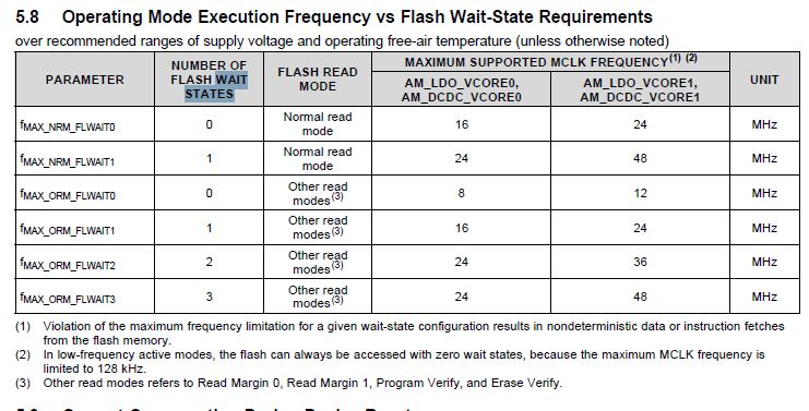
  // request power active mode LDO VCORE1 to support the 48 MHz frequency
  PCMCTL0 = (PCMCTL0&~0xFFFF000F) |     // clear PCMKEY bit field and AMR bit field
            0x695A0000 |                // write the proper PCM key to unlock write access
            0x00000001;                 // request power active mode LDO VCORE1
  // check if the transition is invalid (see Figure 7-3 on p344 of datasheet)
  if(PCMIFG&0x00000004){
    IFlags = PCMIFG;                    // bit 2 set on active mode transition invalid; bits 1-0 are for LPM-related errors; bit 6 is for DC-DC-related error
    PCMCLRIFG = 0x00000004;             // clear the transition invalid flag
    // to do: look at CPM bit field in PCMCTL0, figure out what mode you're in, and step through the chart to transition to the mode you want
    // or be lazy and do nothing; this should work out of reset at least, but it WILL NOT work if Clock_Int32kHz() or Clock_InitLowPower() has been called
    return;
  }
  // wait for the CPM (Current Power Mode) bit field to reflect a change to active mode LDO VCORE1
  while((PCMCTL0&0x00003F00) != 0x00000100){
    CPMwait = CPMwait + 1;
    if(CPMwait >= 500000){
      return;                           // time out error
    }
  }
  // wait for the PCMCTL0 and Clock System to be write-able by waiting for Power Control Manager to be idle
  while(PCMCTL1&0x00000100){
    Postwait = Postwait + 1;
    if(Postwait >= 100000){
      return;                           // time out error
    }
  }
  // initialize PJ.3 and PJ.2 and make them HFXT (PJ.3 built-in 48 MHz crystal out; PJ.2 built-in 48 MHz crystal in)
  PJSEL0 |= 0x0C;
  PJSEL1 &= ~0x0C;                      // configure built-in 48 MHz crystal for HFXT operation
//  PJDIR |= 0x08;                        // make PJ.3 HFXTOUT (unnecessary)
//  PJDIR &= ~0x04;                       // make PJ.2 HFXTIN (unnecessary)
  CSKEY = 0x695A;                       // unlock CS module for register access
  CSCTL2 = (CSCTL2&~0x00700000) |       // clear HFXTFREQ bit field
           0x00600000 |                 // configure for 48 MHz external crystal
           0x00010000 |                 // HFXT oscillator drive selection for crystals >4 MHz
           0x01000000;                  // enable HFXT
  CSCTL2 &= ~0x02000000;                // disable high-frequency crystal bypass
  // wait for the HFXT clock to stabilize
  while(CSIFG&0x00000002){
    CSCLRIFG = 0x00000002;              // clear the HFXT oscillator interrupt flag
    Crystalstable = Crystalstable + 1;
    if(Crystalstable > 100000){
      return;                           // time out error
    }
  }
  CSCTL1 = 0x20000000 |                 // configure for SMCLK divider /4
           0x00100000 |                 // configure for HSMCLK divider /2
           0x00000200 |                 // configure for ACLK sourced from REFOCLK
           0x00000050 |                 // configure for SMCLK and HSMCLK sourced from HFXTCLK
           0x00000005;                  // configure for MCLK sourced from HFXTCLK
  CSKEY = 0;                            // lock CS module from unintended access
}

void main(void)
{
	WDT_A->CTL = WDT_A_CTL_PW | WDT_A_CTL_HOLD;		// stop watchdog timer
	Clock_Init48MHz();
	P4SEL0 |= 0X08;
	P4SEL1 &= ~0X08;
	P4DIR |= 0x08;
	while(1){};
}
to.