Please help me design an analog front end for the waveform in the image below. The frequency is 200kHz. I should be able to change the phase of the waveform using the digital output from the mcu.
This thread has been locked.
If you have a related question, please click the "
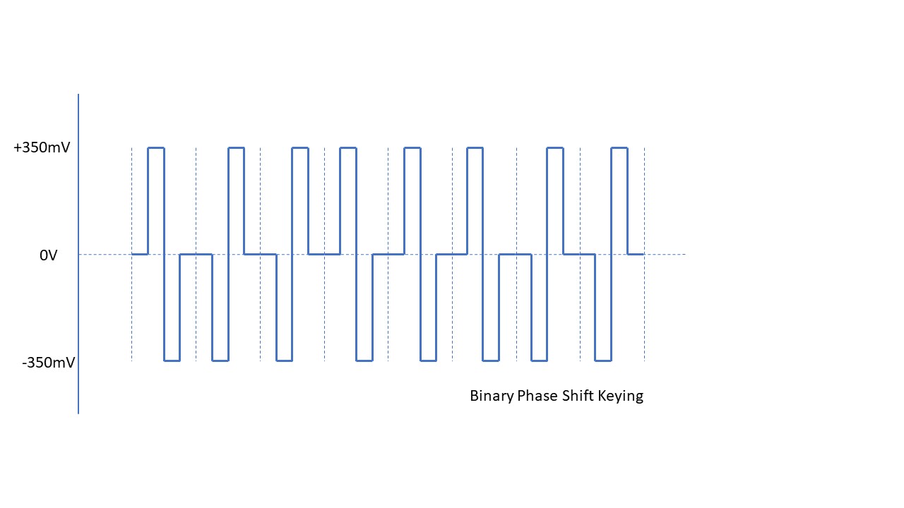
Ask a related question" button in the top right corner. The newly created question will be automatically linked to this question.
Please help me design an analog front end for the waveform in the image below. The frequency is 200kHz. I should be able to change the phase of the waveform using the digital output from the mcu.
The analog circuitry for this is somewhat out of the scope of this forum. Since the diagram above referenes BPSK, I would first start with the digital-side implementation using the BPSK app note here.
I'll have a look at the TI parts & application note collections to see if there's anything that would help you in your design.
Regards,
Bob Landers
Any advice or clue on how I can generate the waveform will be helpful. I have reattached the drawing with the missing data. The BPSK in that application note uses a sine wave carrier. The data I got doesn't have any carrier wave, just 3 voltage levels. Is there a way I can jump between the voltage levels quickly enough to generate the desired waveform.
I found a similiar E2E post that may provide some further information on generating BPSK waveforms.
Please see this post , which uses a DAC5687 that is capable of outputting a signal in the range you specify.
That should provide enough information for you to build a circuit to generate the BPSK output.
Regards,
Bob
**Attention** This is a public forum