This thread has been locked.

If you have a related question, please click the "Ask a related question" button in the top right corner. The newly created question will be automatically linked to this question.

MSP430FR6989: MPU Problem

Part Number: MSP430FR6989

Hi,

At the moment I'm facing problems with the MPU. My Init routine looks like this:


extern uint16_t lcf_crcMem_begin;
#define beginSegment2  &lcf_crcMem_begin

extern uint16_t lcf_code_forbidden_begin;
#define beginSegment3   &lcf_code_forbidden_begin

int16_t _system_pre_init(void)
{
    /* Insert your low-level initializations here */
    /* Disable Watchdog timer to prevent reset during */
    /* long variable initialization sequences. */
    WDTCTL = WDTPW | WDTHOLD;
#ifdef halInterface_assembledVersion_radio
    // Configure MPU
    MPUCTL0 = MPUPW; // Write PWD to access MPU registers
    MPUSEGB1 = (uint16_t)(((uint32_t)beginSegment2) >> 4);
    MPUSEGB2 = (uint16_t)(((uint32_t)beginSegment3) >> 4); // Borders are assigned to segments
    // Segment 1 Allows read and write only
    // Segment 2 Allows read and execute only
    // Segment 3 Allows read and execute only
    MPUSAM =    MPUSEG1WE | MPUSEG1RE | MPUSEG1XE |
                MPUSEG2WE | MPUSEG2RE | MPUSEG2XE |
                MPUSEG3WE | MPUSEG3RE | MPUSEG3XE;
    MPUCTL0 = MPUPW | MPUENA | MPUSEGIE; // Enable MPU protection
    // MPU registers locked until BOR
#endif
    /*==================================*/
    /* Choose if segment initialization */
    /* should be done or not. */
    /* Return: 0 to omit initialization */
    /* 1 to run initialization */
    /*==================================*/
   return 1;

}

lcf_crcMem_begin              -> is 0x6800

lcf_code_forbidden_begin      -> is 0x68C0

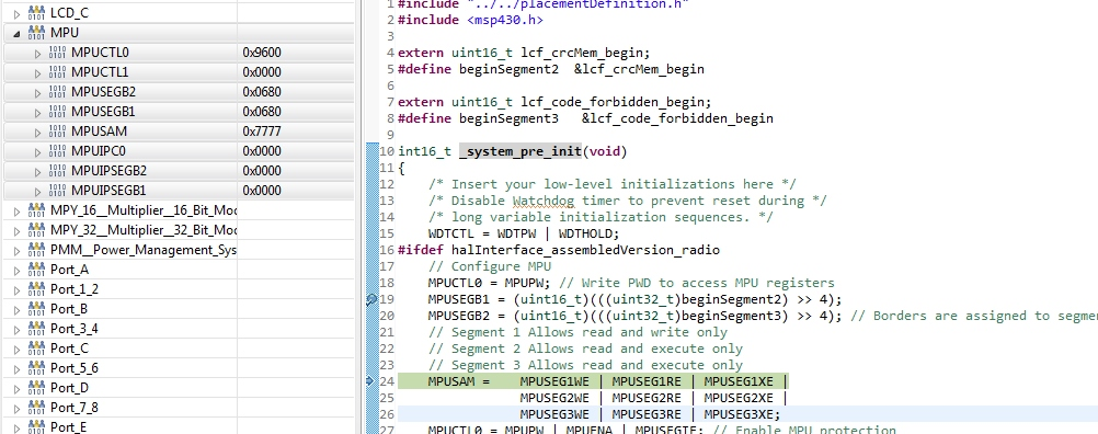
For the first test I allowed everything for all segments. But I get resets all the time.

I see in MPUSEG1 that the address is written correctly (0x0680) but in MPUSEG2 is also written 0x0680 although there should be 0x068C. In datasheet there is a hint that only bit 6-13 should be taken. So this is OK for this example. Where is the problem?

Kind regards

  • Hi tunguskar,

    The MPU only goes down to a granularity of 0x400 increments, which is why MPUSEGB2 0x068C (for address 0x68C0) was turned into 0x0680 (address 0x6800).

    Are you aware of the MPU tool built into CCS? Instead of manually implementing MPU protection as you are doing, it is much simpler to simply use that. What is your use-case? Do you simply have some variables/arrays that you would like to have read-write access in FRAM, while everything else is protected? If this is the case, I would recommend in CCS to use #pragma PERSISTENT (x) where x is your array or variable. Then, in CCS under Project > Properties > General > MPU tab, select the default setting to enable the MPU but let the compiler handle the segmentation. In your C code, remove all the MPU init from the _system_pre_init because the tool will initialize the MPU instead, and for using your FRAM variable or array you can simply access the variable or array as if it were a normal variable or array in RAM - you don't even need to know what address it is placed at. E.g. fram_variable[4] = a++; just like it was an array in RAM.

    There is more information here: e2e.ti.com/.../1707393

    Regards,
    Katie
  • Hi Katie,

    Thanks for the hint with the 0x400 i thought it is just limited by the usable bits 6-12. But shouldn't the code run even with the wrong Settings(segment 1 and two have the same address), because i granted all rights to all three segments?

    We do have a lot of FRAM Sections placed in the linker command file. So my intention in first place is to know whats going on and handle it by my own. We are facing corrupt FRAM segments and the first step was to protect certain areas to see if this is a problem of our code or a physical problem of the device with some strange environment influences.

    Regards

    Christian

  • Hi Christian,

    Yes with all access rights set I would not expect a reset due to MPU violation. Can you tell at what point in the code execution the reset occurs - can we be sure it is an MPU segment access violation triggering the reset, or could it be MPU password or even a totally different cause? If you can check SYSRSTIV register right after the reset occurs, you'll be able to tell what triggered the reset, so you'll be able to tell if it was the MPU that caused it or something else. There are separate values even for MPUPW violation vs MPU segment violation for each of the 3 MPU segments. Could you read SYSRSTIV into a variable at the top of main and then report back? There is a list of SYSRSTIV values in the device datasheet www.ti.com/lit/gpn/msp430fr6989 in Table 6-10 System Module Interrupt Vector Registers.

    Regards,

    Katie

  • Hi Katie,

    The Reset comes from our routine because there was an allocation error. All hour LowLevel drivers allocate and free their usage. In this case the problem is, that the the variable:

    #define COMPE_DEFAULTSTRUCT_ADDRESS                  (0xFFFF)

    static comparatorE_allocStruct_t *allocCompPointerToStruct = (comparatorE_allocStruct_t*)COMPE_DEFAULTSTRUCT_ADDRESS;

    is not correctly initialized(the comparator driver says it is already allocated). in this variable should be the value 0xFFFF on system start. But with activated MPU there isn't this value. When the MPU is going to be deactivated everything is fine. 

    Regards

    Christian 

  • Hi tunguskar,

    Are you trying to set a struct to be at the address 0xFFFF? This address cannot be used because this address contains the reset vector for the device (at 0xFFFE-FFFF). The addresses 0xFF80-FFFF should be reserved in your linker file for JTAG/IPE passwords and the interrupt vector table for the device, and should not be used for anything else.

    It would make more sense to place all variable information that should go into FRAM into a segment together - you can specify section in your linker cmd file and then in your c code use things like #pragma DATA_SECTION(x, ".my_sect") to place things into the sections together. There is more information in www.ti.com/lit/pdf/slau132

    You mention that your drivers allocate and free their usage. But you would still need to make sure that anything you want to put in FRAM is placed in the correct linker command sections and that those sections are then grouped such that you can configure your MPU to know which addresses should be read-write-able or protected.

    Regards,

    Katie

  • 0xFFFF is the base address and should never be used. The Problem is, that when the MPU is active the default target address(0xFFFF) is corrupt, or the debugger shows the value incorrect). 

    Unfortunately we are not able/allowed to set all variable into one area. In my opinion the FRAM order is grouped correctly.

  • Hi tunguskar,

    Can you provide details of how much FRAM area you need for variables / read+write access? I can then help to provide some guidance on how to set this up in your device.

    Regards,

    Katie

**Attention** This is a public forum