This thread has been locked.

If you have a related question, please click the "Ask a related question" button in the top right corner. The newly created question will be automatically linked to this question.

MSP430FR5994: USCI_B1 SPI Communication Issue

Part Number: MSP430FR5994


Hello Guys,

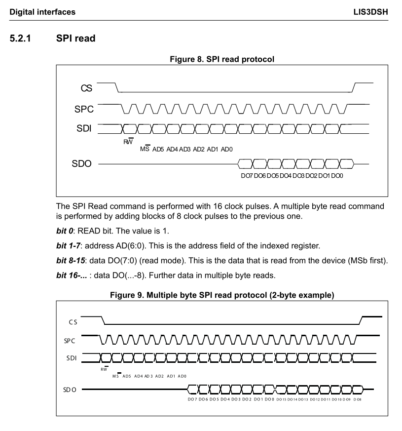
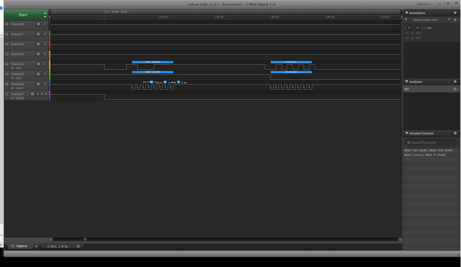
I am trying to interface MSP430FR5994 LP with LIS3DSH accelerometer over SPI communication as this is my first hands on attempt on this set of hardware. I am successfully transmitting data at 1MHz. All I am trying to do is read register (WHO_AM_I) from address 0x0F which is read only device id and should always return 0x3F. So after sending dummy byte as 0x00 it always returns 0x00. I tried sending other test data but it always replies with 0s. And I am not sure what could be wrong. Please help, thanks in advance.

/*
 * File:    main.c
 * Author:  Anand
 */


// ***** includes *****
#include <stdio.h>
#include <stdint.h>
#include "msp430fr5994.h"

#include "spi.h"

// ***** defines *****
#define SPI_TIMEOUT 1234

uint16_t who_am_i;

// ***** private function prototypes *****
void main(void);
void clock_init(void);

// ***** private function definitions *****

/*
 * @brief   XT1 Setup
 * @param   None
 * @return  None
 */
void clock_init (void)
{
    CSCTL0_H = CSKEY_H;                         // Unlock CS registers -----|
                                                //                          |
    CSCTL1 = DCOFSEL_0;                         // Set DCO to 1MHz          |
    CSCTL1 &= ~DCORSEL;                         //                          |
                                                //                          |
    CSCTL2 = SELA__LFXTCLK; // LFXTCLK when available, otherwise VLOCLK     |
    CSCTL2 |= SELS__DCOCLK; // DCOCLK                                       |
    CSCTL2 |= SELM__DCOCLK; // DCOCLK                                       |
                                                //                          |
    CSCTL3 = DIVA__1 | DIVS__1 | DIVM__1;       // Set all dividers         |
                                                //                          |
    CSCTL4 &= ~LFXTOFF;                 // LFXT is on if LFXT is selected   |
                                                //                          |
    do                                          //                          |
    {                                           //                          |
        CSCTL5 &= ~LFXTOFFG;                    // Clear XT1 fault flag     |
        SFRIFG1 &= ~OFIFG;                      //                          |
    }                                           //                          |
    while (SFRIFG1 & OFIFG);                    // Test fault flag          |
                                                //                          |
    CSCTL0_H = 0;                               // Lock CS registers -------|
}

/*
 * @brief   This is the main function
 * @param   None
 * @return  None
 */
void main (void)
{
    WDTCTL = WDTPW | WDTHOLD;	// Stop the watch dog timer

    // Configure GPIO
    spi_b_gpio_init();

    
    // Initialize the clock
    clock_init();

    // Disable the GPIO power-on default high-impedance mode to activate
    // previously configured port settings
    PM5CTL0 &= ~LOCKLPM5;

    // Initialize the USCI_B1 for SPI operation
    spi_b_init();

    P8DIR = 0xFF;                           // Port 8 as output 
    P8OUT = 0x00;                           // Port 8 as low outout

    UCB1TXBUF = 0x0F | 0x80;                // Transmit characters | R/W bit

    uint16_t spi_timeout = SPI_TIMEOUT;

    while((UCB1STATW && UCBUSY) && (spi_timeout > 0))
    {
        spi_timeout--;
    }

    if(spi_timeout == 0)
    {
        printf("spi 1 transmit failed \n");
    }

    UCB1TXBUF = 0x00;                       // Transmit characters

    spi_timeout = SPI_TIMEOUT;

    while((UCB1STATW && UCBUSY) && (spi_timeout > 0))
    {
        spi_timeout--;
    }

    if(spi_timeout == 0)
    {
        printf("spi 2 transmit failed \n");
    }
    else
    {
        printf("spi 2 transmit time: %u \n", spi_timeout);
    }

    who_am_i = UCB1RXBUF;

    printf("exiting main \n");

    return ;
}

  • I don't see spi_b_init() here, but based on your Analyzer Settings I suspect you have the clock phase (UCCKPH) backwards. (In a pinch: Try all the settings. There are only 4 of them.)

    Unsolicited:

    > while((UCB1STATW && UCBUSY) && (spi_timeout > 0))

    This only works by accident. Try:

    > while((UCB1STATW & UCBUSY) && (spi_timeout > 0))

  • Hello Bruce,

    Here are my settings to initialize the SPI communication.

    /*
     * @brief   Configure USCI_B1 for SPI operation
     * @param   None
     * @return  None
     */
    void spi_b_init (void)
    {
        UCB1CTLW0 = UCSWRST;        // Put state machine in reset --------------|
                                                                              //|
        UCB1CTLW0 |= UCCKPH;                                                  //|
        UCB1CTLW0 |= UCCKPL;        // The inactive state is high               |
        UCB1CTLW0 |= UCMSB;         // MSB first                                |
        UCB1CTLW0 |= UCMST;         // Master mode                              |
        UCB1CTLW0 |= UCMODE_2;      // 4-pin SPI Slave enabled at UCxSTE = 0    |
        UCB1CTLW0 |= UCSYNC;        // Synchronous mode                         |
        UCB1CTLW0 |= UCSTEM;        // STE generate enable signal for slave     |
        UCB1CTLW0 |= UCSSEL__SMCLK; // SMCLK                                    |
                                                                              //|
        UCB1BRW = 0x01;             // /1                                       |
                                                                              //|
        UCB1CTLW0 &= ~UCSWRST;      // Release for operation -------------------|
    }
    

    Also, I have changed the code for the while loop with single &, thanks for correcting me. For reference here is the SPI read from the accelerometer datasheet.

  • As I read LIS3DH DS sec 6.2 and SLAU367L Table 25-12, UCCKPH should be 0. Did you try it that way?
  • Yes, I tried that way too. By default on reset UCCKPH will be set to 0. I tried overwriting it as:

    /*
     * @brief   Configure USCI_B1 for SPI operation
     * @param   None
     * @return  None
     */
    void spi_b_init (void)
    {
        UCB1CTLW0 = UCSWRST;        // Put state machine in reset --------------|
                                                                              //|
        UCB1CTLW0 &= ~(UCCKPH);                                               //|
        UCB1CTLW0 |= UCCKPL;        // The inactive state is high               |
        UCB1CTLW0 |= UCMSB;         // MSB first                                |
        UCB1CTLW0 |= UCMST;         // Master mode                              |
        UCB1CTLW0 |= UCMODE_2;      // 4-pin SPI Slave enabled at UCxSTE = 0    |
        UCB1CTLW0 |= UCSYNC;        // Synchronous mode                         |
        UCB1CTLW0 |= UCSTEM;        // STE generate enable signal for slave     |
        UCB1CTLW0 |= UCSSEL__SMCLK; // SMCLK                                    |
                                                                              //|
        UCB1BRW = 0x01;             // /1                                       |
                                                                              //|
        UCB1CTLW0 &= ~UCSWRST;      // Release for operation -------------------|
    }

  • You mentioned that your (register) writes were succeeding. How did you test this (in the absence of being able to read them back)?

    I'm also a bit concerned about that low pulse on MOSI as you're starting the transaction. What's interesting is that this generates an I2C START condition inside the LIS3DH. One supposes that once you assert /CS it will switch mode to SPI flawlessly, but I'm not sure I would bet my project on it.

    I presume this pulse has to do with what spi_b_gpio_init() -- which I don't see here -- is doing. Even so, I suspect that if you move the LOCKLPM5 clearing to follow spi_b_init() that pulse will disappear.
  • Oh, and: Just for fun, try writing a "dummy" (second) byte that isn't 0x00. Something distinctive, like 0x5A maybe.
  • I have not tried to write the data to the device registers yet. I meant that when reading a register, I can see correct data is going out. Also, I believe that P5.3 is CS line chose in the original example code, but as that pin is not accessible on the breakout dev board, so I am using P8.3 as CS line and manually controlling it.

    /*
     * @brief   Configure USCI_B1 SPI GPIO operation
     * @param   None
     * @return  None
     */
    void spi_b_gpio_init (void)
    {
        P5SEL1 &= ~(BIT0 | BIT1 | BIT2 | BIT3); // USCI_B1 SCLK, MOSI,
        P5SEL0 |= (BIT0 | BIT1 | BIT2 | BIT3);  // STE, and MISO pin
        PJSEL0 |= BIT4 | BIT5;
    }

    I tried sending dummy byte as 0x55, and still got 0s back.

  • Did moving the LOCKLPM5 statement get rid of that extra MOSI pulse? You could (probably should) also move the spi_b_gpio_init() call to follow the spi_b_init() call, to get the same effect.

    You probably don't want to use UCSTEM in this application. It only provides 1-byte transactions, and the LIS3DH transactions are all >1 byte. You should plan on explicitly controlling the /CS pin as a GPIO. (You could use P5.3, or P8.3, or whatever is convenient.)
  • I tried moving LOCKLPM5, but no effect on the data returned from the acceleratorometer. Here is the updated code:

    /*
     * File:    main.c
     * Author:  Anand
     */
    
    
    // ***** includes *****
    #include <stdio.h>
    #include <stdint.h>
    #include "msp430fr5994.h"
    
    #include "spi.h"
    
    // ***** defines *****
    #define SPI_TIMEOUT     1234
    #define SPI_READ_BIT    0x80
    
    uint16_t who_am_i;
    
    // ***** private function prototypes *****
    void main(void);
    void clock_init(void);
    
    // ***** private function definitions *****
    
    /*
     * @brief   XT1 Setup
     * @param   None
     * @return  None
     */
    void clock_init (void)
    {
        CSCTL0_H = CSKEY_H;                         // Unlock CS registers -----|
        //                          |
        CSCTL1 = DCOFSEL_0;                         // Set DCO to 1MHz          |
        CSCTL1 &= ~DCORSEL;                         //                          |
        //                          |
        CSCTL2 = SELA__LFXTCLK; // LFXTCLK when available, otherwise VLOCLK     |
        CSCTL2 |= SELS__DCOCLK; // DCOCLK                                       |
        CSCTL2 |= SELM__DCOCLK; // DCOCLK                                       |
        //                          |
        CSCTL3 = DIVA__1 | DIVS__1 | DIVM__1;       // Set all dividers         |
        //                          |
        CSCTL4 &= ~LFXTOFF;                 // LFXT is on if LFXT is selected   |
        //                          |
        do                                          //                          |
        {                                           //                          |
            CSCTL5 &= ~LFXTOFFG;                    // Clear XT1 fault flag     |
            SFRIFG1 &= ~OFIFG;                      //                          |
        }                                           //                          |
        while (SFRIFG1 & OFIFG);                    // Test fault flag          |
        //                          |
        CSCTL0_H = 0;                               // Lock CS registers -------|
    }
    
    /*
     * @brief   This is the main function
     * @param   None
     * @return  None
     */
    void main (void)
    {
        WDTCTL = WDTPW | WDTHOLD;	// Stop the watch dog timer
    
        // Initialize the clock
        //clock_init();
    
        P8DIR = 0xFF;                           // Port 8 as output
        P8OUT = 0x00;                           // Port 8 as low output
    
        // Configure GPIO
        spi_b_gpio_init();
    
        // Initialize the USCI_B1 for SPI operation
        spi_b_init();
    
        // Disable the GPIO power-on default high-impedance mode to activate
        // previously configured port settings
        PM5CTL0 &= ~LOCKLPM5;
    
        UCB1TXBUF = 0x0F | SPI_READ_BIT;        // Transmit characters | R/W bit
    
        uint16_t spi_timeout = SPI_TIMEOUT;
    
        while((UCB1STATW & UCBUSY) && (spi_timeout > 0))
        {
            spi_timeout--;
        }
    
        if(spi_timeout == 0)
        {
            printf("spi 1 transmit failed \n");
        }
    
        UCB1TXBUF = 0x55;                       // Transmit characters
    
        spi_timeout = SPI_TIMEOUT;
    
        while((UCB1STATW & UCBUSY) && (spi_timeout > 0))
        {
            spi_timeout--;
        }
    
        if(spi_timeout == 0)
        {
            printf("spi 2 transmit failed \n");
        }
    
        who_am_i = UCB1RXBUF;
    
        P8OUT = 0xFF;                           // Port 8 as high output
    
        printf("exiting main \n");
    
        while(1)
        {
    
        }
    
        return ;
    }
    
    /*
     * @brief   Configure USCI_B1 SPI GPIO operation
     * @param   None
     * @return  None
     */
    void spi_b_gpio_init (void)
    {
        P5SEL1 &= ~(BIT0 | BIT1 | BIT2 | BIT3); // USCI_B1 SCLK, MOSI,
        P5SEL0 |= (BIT0 | BIT1 | BIT2 | BIT3);  // STE, and MISO pin
        PJSEL0 |= BIT4 | BIT5;
    }
    
    /*
     * @brief   Configure USCI_B1 for SPI operation
     * @param   None
     * @return  None
     */
    void spi_b_init (void)
    {
        UCB1CTLW0 = UCSWRST;        // Put state machine in reset --------------|
                                                                              //|
        UCB1CTLW0 &= ~(UCCKPH);                                               //|
        UCB1CTLW0 |= UCCKPL;        // The inactive state is high               |
        UCB1CTLW0 |= UCMSB;         // MSB first                                |
        UCB1CTLW0 |= UCMST;         // Master mode                              |
        UCB1CTLW0 |= UCMODE_2;      // 4-pin SPI Slave enabled at UCxSTE = 0    |
        UCB1CTLW0 |= UCSYNC;        // Synchronous mode                         |
        UCB1CTLW0 |= UCSTEM;        // STE generate enable signal for slave     |
        UCB1CTLW0 |= UCSSEL__SMCLK; // SMCLK                                    |
                                                                              //|
        UCB1BRW = 0x01;             // /1                                       |
                                                                              //|
        UCB1CTLW0 &= ~UCSWRST;      // Release for operation -------------------|
    }
    

    I am driving /CS manually using P8.3, and here is the new capture from the logic analyzer.

  • I suggest you move the spi_b_gpio_init call to follow the call to spi_b_init. I think that will get rid of that stray MOSI pulse completely.

    Is this a commercial breakout board? Is anything else connected to/on it?

    The fact that the LIS3DH is driving MISO at the right time suggests that it is seeing the first (R/W) bit of the first byte. Try reading all of the registers by sending a 0xC0 first, then sending 64 dummy bytes. There may be a clue in the result. (Does it ever output anything but 0?)
  • I have connected my MSP430FR5994 to LIS3DSH, and here are the connections I have made via jumper wires:

    Vdd_IO and VCC are connected to 3V3, Gnd to Gnd, CS to P8.3, SCL to P5.2, SDA to P5.0 and SDO to P5.1

    I made the code changes accordingly and here is the updated code:

    /*
     * File:    main.c
     * Author:  Anand
     */
    
    
    // ***** includes *****
    #include <stdio.h>
    #include <stdint.h>
    #include "msp430fr5994.h"
    
    #include "spi.h"
    
    // ***** defines *****
    #define SPI_TIMEOUT     1234
    #define SPI_READ_BIT    0x80
    
    uint16_t who_am_i;
    
    // ***** private function prototypes *****
    void main(void);
    void clock_init(void);
    
    // ***** private function definitions *****
    
    /*
     * @brief   XT1 Setup
     * @param   None
     * @return  None
     */
    void clock_init (void)
    {
        CSCTL0_H = CSKEY_H;                         // Unlock CS registers -----|
        //                          |
        CSCTL1 = DCOFSEL_0;                         // Set DCO to 1MHz          |
        CSCTL1 &= ~DCORSEL;                         //                          |
        //                          |
        CSCTL2 = SELA__LFXTCLK; // LFXTCLK when available, otherwise VLOCLK     |
        CSCTL2 |= SELS__DCOCLK; // DCOCLK                                       |
        CSCTL2 |= SELM__DCOCLK; // DCOCLK                                       |
        //                          |
        CSCTL3 = DIVA__1 | DIVS__1 | DIVM__1;       // Set all dividers         |
        //                          |
        CSCTL4 &= ~LFXTOFF;                 // LFXT is on if LFXT is selected   |
        //                          |
        do                                          //                          |
        {                                           //                          |
            CSCTL5 &= ~LFXTOFFG;                    // Clear XT1 fault flag     |
            SFRIFG1 &= ~OFIFG;                      //                          |
        }                                           //                          |
        while (SFRIFG1 & OFIFG);                    // Test fault flag          |
        //                          |
        CSCTL0_H = 0;                               // Lock CS registers -------|
    }
    
    /*
     * @brief   This is the main function
     * @param   None
     * @return  None
     */
    void main (void)
    {
        WDTCTL = WDTPW | WDTHOLD;	// Stop the watch dog timer
    
        // Initialize the clock
        //clock_init();
    
        P8DIR = 0xFF;                           // Port 8 as output
        P8OUT = 0x00;                           // Port 8 as low output
    
        // Initialize the USCI_B1 for SPI operation
        spi_b_init();
    
        // Configure GPIO
        spi_b_gpio_init();
    
        // Disable the GPIO power-on default high-impedance mode to activate
        // previously configured port settings
        PM5CTL0 &= ~LOCKLPM5;
    
        UCB1TXBUF = 0xC0 | SPI_READ_BIT;        // Transmit characters | R/W bit
    
        uint16_t spi_timeout = SPI_TIMEOUT;
    
        while((UCB1STATW & UCBUSY) && (spi_timeout > 0))
        {
            spi_timeout--;
        }
    
        if(spi_timeout == 0)
        {
            printf("spi -1 transmit failed \n");
        }
    
        uint8_t index = 0u;
        uint16_t received_data[64];
    
        for(index=0u; index<64u; index++)
        {
            UCB1TXBUF = 0x55;                       // Transmit characters
    
            spi_timeout = SPI_TIMEOUT;
    
            while((UCB1STATW & UCBUSY) && (spi_timeout > 0))
            {
                spi_timeout--;
            }
    
            if(spi_timeout == 0)
            {
                printf("spi %u transmit failed \n", index);
            }
    
            received_data[index] = UCB1RXBUF;
        }
    
        //who_am_i = UCB1RXBUF;
    
        P8OUT = 0xFF;                           // Port 8 as high output
    
        printf("exiting main \n");
    
        return ;
    }
    
    /*
     * @brief   Configure USCI_B1 SPI GPIO operation
     * @param   None
     * @return  None
     */
    void spi_b_gpio_init (void)
    {
        P5SEL1 &= ~(BIT0 | BIT1 | BIT2 | BIT3); // USCI_B1 SCLK, MOSI,
        P5SEL0 |= (BIT0 | BIT1 | BIT2 | BIT3);  // STE, and MISO pin
        PJSEL0 |= BIT4 | BIT5;
    }
    
    /*
     * @brief   Configure USCI_B1 for SPI operation
     * @param   None
     * @return  None
     */
    void spi_b_init (void)
    {
        UCB1CTLW0 = UCSWRST;        // Put state machine in reset --------------|
                                                                              //|
        UCB1CTLW0 &= ~(UCCKPH);                                               //|
        UCB1CTLW0 |= UCCKPL;        // The inactive state is high               |
        UCB1CTLW0 |= UCMSB;         // MSB first                                |
        UCB1CTLW0 |= UCMST;         // Master mode                              |
        UCB1CTLW0 |= UCMODE_2;      // 4-pin SPI Slave enabled at UCxSTE = 0    |
        UCB1CTLW0 |= UCSYNC;        // Synchronous mode                         |
        UCB1CTLW0 |= UCSTEM;        // STE generate enable signal for slave     |
        UCB1CTLW0 |= UCSSEL__SMCLK; // SMCLK                                    |
                                                                              //|
        UCB1BRW = 0x01;             // /1                                       |
                                                                              //|
        UCB1CTLW0 &= ~UCSWRST;      // Release for operation -------------------|
    }
    

    And the capture from the logic analyzer:

    https://www.dropbox.com/s/8ne15zj3o2ps8p7/0xC0.logicdata?dl=0

  • I can't read that capture file. What does it say?
  • The file I sent earlier can be by the logic analyzer. It has the capture as follows

  • The resolution in the .PNG doesn't really show whether the stray MOSI pulse is gone, but it should be. (I don't have your logic analyzer, so I can't fool with the signal myself.)

    At least it's evident that the device is capable of producing non-zeros. The results on the lower right don't look quite proper -- even the MOSI data seems to be skewed, which it wasn't before. You might want to re-check the Analysis parameters. (Note: UCCKPH=0 corresponds to CPHA=1.)

    What did you get in your received_data[] array? There's no big mystery here -- I'm anticipating finding a 0x33 somewhere in there, perhaps shifted/inverted/smeared and presumably not in element [15].
  • Some other things to check:

    1) How long are your patch wires? If they're more than maybe 3 inches long, try slowing down the SPI.
    2) Where are your logic analyzer probes connected? If they're at the MCU board pins, try probing at the breakout board pins instead.
  • Right, I have already set the CPHA to 1. Here are the contents of the received_data array:

    And I was able to export the data captured by the logic analyzer in CSV format. Here's the link to it:

    https://www.dropbox.com/s/jj9c1w8kfm18ccv/Capture_0xC0.csv?dl=0

    My patch wires are about 6 inches long. The accelerometer is capable of communicating at 10Mhz at max, I have SPI clock set at 1MHz. I was probing at MCU initially. If I switch them to the breakout board, I don't see any change.

  • Slowing the SPI down isn't for the device, it's for the wiring. A slower SPI is more forgiving of long wires, questionable solder joints, and pullups.

    Start with, say BRW=4 (250kHz), then 20 (50kHz), then 50 (20kHz), and watch for any change in behavior.
  • I tried slowing down the SPI communication with the baud rates you have suggested, but no change in the behavior. 

  • So received_data[] looks identical at 20kHz?

    All the same, I still suspect something electrical. If you have spare patch wires, this is the time to try them.

    Is this a commercial breakout board?
  • Yes, received data looks same. On the other hand, if I try to communicate with the same accelerometer using analog discovery or bus pirate, I get the correct data back. Yes, it's a commercial breakout board.

  • Great. (Though I didn't really think the chip was broken.) How is your Bus Pirate setup different? How are the waveforms different?

    > Yes, it's a commercial breakout board.
    Which one? I know of at least four of them (all different).

    Incidentally: You mentioned you were using the FR5994 Launchpad, but P5.3 wasn't available. My Launchpads have P5.3 exposed on J2. Are we looking at the same boards?
  • Bruce, sorry for the late reply.

    The problem was with the accelerometer LIS3DSH. It was correctly reposting WHO_AM_I register only. Later when I tried to write some test data to it, still it always returned back 0s. Now I am using Kionix KX122-1037 accelerometer, and the SPI driver just worked fine.

    Updated SPI driver:

    /*
     *       file: spi.c
     * Created on: Sep 12, 2017
     *     Author: Anand
     */
    
    // ***** includes *****
    #include <stdio.h>
    #include <stdbool.h>
    #include <stdint.h>
    #include "msp430fr5994.h"
    
    // ***** defines *****
    #define SPI_TIMEOUT     1234
    #define SPI_READ_BIT    0x80
    #define SPI_WRITE_BIT   0x7F
    
    void delay (void)
    {
        static uint16_t counter = SPI_TIMEOUT;
    
        while(counter > 0)
        {
            counter--;
        }
    }
    
    /*
     * @brief   Configure USCI_B1 SPI GPIO operation
     * @param   None
     * @return  None
     */
    void spi_b_gpio_init (void)
    {
        P8DIR = 0xFF;                           // Port 8 as output for CS on P8.3
    
        P5SEL1 &= ~(BIT0 | BIT1 | BIT2 | BIT3); // USCI_B1 SCLK, MOSI,
        P5SEL0 |= (BIT0 | BIT1 | BIT2 | BIT3);  // STE, and MISO pin
        PJSEL0 |= BIT4 | BIT5;
    
        /*
        P5DIR |= (BIT0 | BIT2);
    
        // Enable the pull-ups on the SOMI input
        P5REN |= BIT1;
        P5OUT |= BIT1;
        */
    
        // Accelerometer interrupt will come on P4.1
        P7SEL0 &= ~(BIT3) ;     // P4.1 as GPIO
        P7SEL1 &= ~(BIT3) ;     // P4.1 as GPIO
        P7DIR &= ~(BIT3);       // P4.1 SEL as Input
        P7IE |= BIT3;           // Enable the interrupt on P4.1
        P7IES &= ~(BIT3) ;      // Rising edge
        P7IFG &= (~BIT3);       // Clear interrupt flag for P7.3;
    }
    
    /*
     * @brief   Configure USCI_B1 for SPI operation
     * @param   None
     * @return  None
     */
    void spi_b_init (void)
    {
        UCB1CTLW0 = UCSWRST;        // Put state machine in reset --------------|
        UCB1CTLW0 |= (UCCKPH);                                               //||
        UCB1CTLW0 |= UCMSB;         // MSB first                                |
        UCB1CTLW0 |= UCMST;         // Master mode                              |
        UCB1CTLW0 |= UCMODE_2;      // 4-pin SPI Slave enabled at UCxSTE = 0    |
        UCB1CTLW0 |= UCSYNC;        // Synchronous mode                         |
        UCB1CTLW0 |= UCSTEM;        // STE generate enable signal for slave     |
        UCB1CTLW0 |= UCSSEL__SMCLK; // SMCLK                                    |
        //|
        UCB1BRW = 1;             // /x                                       |
        //|
        UCB1CTLW0 &= ~UCSWRST;      // Release for operation -------------------|
    }
    
    /*
     * @brief   This functions reads the 8 bit register from LIS3DSH accelerometer
     * @param   Register address to be read
     *          Pointer to variable to store register content
     * @return  True if function is successfully executed
     *          False if function is failed
     */
    bool spi_b_read (uint8_t register_address, uint16_t * register_content)
    {
        P8OUT = 0x00;                           // Port 8 as low output
    
        UCB1TXBUF = register_address | SPI_READ_BIT;
    
        uint16_t spi_timeout = SPI_TIMEOUT;
    
        while((UCB1STATW & UCBUSY) && (spi_timeout > 0))
        {
            spi_timeout--;
        }
    
        if(spi_timeout == 0)
        {
            printf("spi reg address transmit failed \n");
            return false;
        }
    
        delay();                                // delay
    
        UCB1TXBUF = 0xFF;                       // dummy byte
    
        spi_timeout = SPI_TIMEOUT;
    
        while((UCB1STATW & UCBUSY) && (spi_timeout > 0))
        {
            spi_timeout--;
        }
    
        if(spi_timeout == 0)
        {
            printf("spi reg content transmit failed \n");
            return false;
        }
    
        * register_content = UCB1RXBUF;
    
        P8OUT = 0xFF;                           // Port 8 as high output
    
        return true;
    }
    
    /*
     * @brief   This functions reads the 8 bit register from LIS3DSH accelerometer
     * @param   Register address to be read
     *          Pointer to variable to store register content
     * @return  True if function is successfully executed
     *          False if function is failed
     */
    bool spi_b_write (uint8_t register_address, uint8_t register_content)
    {
        P8OUT = 0x00;                           // Port 8 as low output
    
        uint16_t spi_timeout = SPI_TIMEOUT;
    
        UCB1TXBUF = register_address & SPI_WRITE_BIT;
    
        while((UCB1STATW & UCBUSY) && (spi_timeout > 0))
        {
            spi_timeout--;
        }
    
        if(spi_timeout == 0)
        {
            printf("spi reg address transmit failed \n");
            return false;
        }
    
        delay();                                // delay
    
        spi_timeout = SPI_TIMEOUT;
    
        UCB1TXBUF = register_content;
    
        while((UCB1STATW & UCBUSY) && (spi_timeout > 0))
        {
            spi_timeout--;
        }
    
        if(spi_timeout == 0)
        {
            printf("spi reg content transmit failed \n");
            return false;
        }
    
        P8OUT = 0xFF;                           // Port 8 as high output
    
        return true;
    }
    

**Attention** This is a public forum