This thread has been locked.

If you have a related question, please click the "Ask a related question" button in the top right corner. The newly created question will be automatically linked to this question.

CCS/MSP432P401R: Should i remove jumpers on the board to run Energy Trace more accurately?

Part Number: MSP432P401R
Other Parts Discussed in Thread: ENERGYTRACE

Tool/software: Code Composer Studio

Hello

Using MSP432P401R, I'm trying to run Energy Trace in CCS "more accurately"

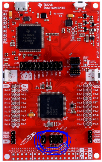
1. To do that, Should i remove those four jumpers on the board??

2. And what if i remove those jumpers, Is there any possibility that generation leak power and current?

  • Hello,
    If you just want to see the current and power then I would recommend disconnecting the JTAG and simply measure the current supplied on 3V3. e2e.ti.com/.../2263388

    If you want to run energyTrace++ and see the mode then you would still need to keep the JTAG connected.

    The pins that you highlight will not impact the power consumption as long as they are driven low (active low). If you drive them high then you will obviously turn on the LEDs and consume power there or if you leave the IO in a high-z state (input) then the IO may float into the threshold region of the schmidt trigger causing switching power losses.

    Chris
  • Hi, Chris. 

    My code is just basic float calculation code, and I run Energy Trace only for a time, energy, power and current. not for a mode.

    So it means that didn't use any GPIO port.

    As you said, LED pins are in active low and it will not impact power losses.

    But depending on the jumpers connection, the EnergyTrace results are different.:(

    And I don't know the reason why.

    Is it really OK that I connect jumpers on the board during the EnergyTrace execution?

  • Hello,

        That is strange.  According to the schematics, driving those pins low should not result in any power loss.

    You can disconnect the LEDs to ensure that no current will flow.  Can you share the power numbers that you are seeing with and without the LED jumpers, so that I can try to recreate?

    Thanks,
    Chris

  • Hello,

    Yes, right. I looked the schematics, too! So i thought that really strange.

    It is sorry for that i left MSP board in my office, so i couldn't capture the result now.

    But i recored the results on the file and those are the EnergyTrace results depending on the LED connection.(remove 4 jumpers or not)

    The numbers of each picture are Time, Energy, Power and current in order.

    As you can see, the values ​​are quite different.

    Am i doing something wrong?

  • I would confirm that the IOs are configured properly. Since the current actually increases in the disconnected state that leads me to believe that the IO are high-z and not being driven low.

    Since you are not using any of the GPIO you could use the following to initialize the IO:
    /*
    * Initialize all outputs (except JTAG) for power consumption
    */
    MAP_GPIO_setAsOutputPin(GPIO_PORT_PA, PIN_ALL16);
    MAP_GPIO_setAsOutputPin(GPIO_PORT_PB, PIN_ALL16);
    MAP_GPIO_setAsOutputPin(GPIO_PORT_PC, PIN_ALL16);
    MAP_GPIO_setAsOutputPin(GPIO_PORT_PD, PIN_ALL16);
    MAP_GPIO_setAsOutputPin(GPIO_PORT_PE, PIN_ALL16);
    MAP_GPIO_setOutputLowOnPin(GPIO_PORT_PA, PIN_ALL16);
    MAP_GPIO_setOutputLowOnPin(GPIO_PORT_PB, PIN_ALL16);
    MAP_GPIO_setOutputLowOnPin(GPIO_PORT_PC, PIN_ALL16);
    MAP_GPIO_setOutputLowOnPin(GPIO_PORT_PD, PIN_ALL16);
    MAP_GPIO_setOutputLowOnPin(GPIO_PORT_PE, PIN_ALL16);

    MAP_GPIO_setAsOutputPin(GPIO_PORT_PJ, GPIO_PIN0+GPIO_PIN1+GPIO_PIN2+
    GPIO_PIN3);
    MAP_GPIO_setOutputLowOnPin(GPIO_PORT_PJ, GPIO_PIN0+GPIO_PIN1+GPIO_PIN2+
    GPIO_PIN3);


    Regards,
    Chris
  • I modified the code and it worked!!!

    Thank you for your help:)

**Attention** This is a public forum