This thread has been locked.
If you have a related question, please click the "Ask a related question" button in the top right corner. The newly created question will be automatically linked to this question.
Part Number: MSP432P401R
Tool/software: TI-RTOS
Hi All,
In my application, msp432 needs to set other devices and communicate with host through SPI and measure voltage with internal ADC.
So I modify the spiloopback example to achieve these functions.
1.remove slavethread
2.add spi/gpio/adc code at masterthread
There are 4 SPI in my application(2 master mode/2 slave mode,UCA0/A2/B0/B2)
When the code runs, it will set external devices through the 2 master SPI. Then the code will enter enter a while(1) loop.
In the while loop, the host SPI(slave mode) will prepare to communicate with host when the spi_host_en(msp432 p1.0) is high.
In my experiment,
1.the master mode SPI will stuck at
transferOK = SPI_transfer( spi_handle_dac1, &spi_trans_dac1 );
After turning bitrate, the code can go to next line. Why? My bitrate range is under 10MHz.
2.In the while loop, if host pulls the spi_host_en high and sends clk to msp432, msp432 always sends the last byte of tx buffer(8 byte).
Is there any configuration error in my code or some constraints on msp432?
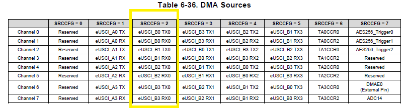
3.In MSP_EXP432P401R.c, I need to add the SPI configuration. But I find the tx/rxDMAChannelIndex for UCA0 in dma.h only have DMA_CH0_EUSCIA0TX/DMA_CH1_EUSCIA0RX.
So if i want to use UCA0, only DMA_CH0_EUSCIA0TX/DMA_CH1_EUSCIA0RX is usable?
/* * Copyright (c) 2015-2016, Texas Instruments Incorporated * All rights reserved. * * Redistribution and use in source and binary forms, with or without * modification, are permitted provided that the following conditions * are met: * * * Redistributions of source code must retain the above copyright * notice, this list of conditions and the following disclaimer. * * * Redistributions in binary form must reproduce the above copyright * notice, this list of conditions and the following disclaimer in the * documentation and/or other materials provided with the distribution. * * * Neither the name of Texas Instruments Incorporated nor the names of * its contributors may be used to endorse or promote products derived * from this software without specific prior written permission. * * THIS SOFTWARE IS PROVIDED BY THE COPYRIGHT HOLDERS AND CONTRIBUTORS "AS IS" * AND ANY EXPRESS OR IMPLIED WARRANTIES, INCLUDING, BUT NOT LIMITED TO, * THE IMPLIED WARRANTIES OF MERCHANTABILITY AND FITNESS FOR A PARTICULAR * PURPOSE ARE DISCLAIMED. IN NO EVENT SHALL THE COPYRIGHT OWNER OR * CONTRIBUTORS BE LIABLE FOR ANY DIRECT, INDIRECT, INCIDENTAL, SPECIAL, * EXEMPLARY, OR CONSEQUENTIAL DAMAGES (INCLUDING, BUT NOT LIMITED TO, * PROCUREMENT OF SUBSTITUTE GOODS OR SERVICES; LOSS OF USE, DATA, OR PROFITS; * OR BUSINESS INTERRUPTION) HOWEVER CAUSED AND ON ANY THEORY OF LIABILITY, * WHETHER IN CONTRACT, STRICT LIABILITY, OR TORT (INCLUDING NEGLIGENCE OR * OTHERWISE) ARISING IN ANY WAY OUT OF THE USE OF THIS SOFTWARE, * EVEN IF ADVISED OF THE POSSIBILITY OF SUCH DAMAGE. */ #include <ti/devices/msp432p4xx/driverlib/driverlib.h> #include <stdint.h> #include <stddef.h> #include <unistd.h> #include <string.h> /* POSIX Header files */ #include <pthread.h> /* Driver Header files */ #include <ti/drivers/GPIO.h> #include <ti/drivers/SPI.h> #include <ti/drivers/Power.h> /* Example/Board Header files */ #include "Board.h" #define THREADSTACKSIZE 768 static pthread_barrier_t barrier; #define SPI_HOST_MSG_LENGTH 7 #define SPI_DAC1_MSG_LENGTH 3 #define SPI_DAC3_MSG_LENGTH 2 #define SPI_VCO_MSG_LENGTH 4 volatile uint32_t cal30; volatile uint32_t cal85; volatile float calDifference; volatile float temperatureReading; volatile float tempF; static uint16_t adc_resultsBuffer[4]/*,adc_d*/; //static uint16_t adc_result_array_ind=0; uint8_t SPI_test_Tx_Buf[SPI_HOST_MSG_LENGTH]={0x55,0xaa,0xaa,0xaa,0xaa,0xaa,0xf5}; uint8_t SPI_test_Rx_Buf[SPI_HOST_MSG_LENGTH]={0}; volatile uint8_t SPI_host_Tx_Buf[SPI_HOST_MSG_LENGTH]={0x19,0x33,0xaa,0xaa,0xaa,0x22,0x76}; volatile uint8_t SPI_host_Rx_Buf[SPI_HOST_MSG_LENGTH]={0}; uint8_t SPI_DAC1_Tx_Buf[SPI_DAC1_MSG_LENGTH],SPI_DAC1_Rx_Buf[SPI_DAC1_MSG_LENGTH]; uint8_t SPI_DAC3_Tx_Buf[SPI_DAC3_MSG_LENGTH],SPI_DAC3_Rx_Buf[SPI_DAC3_MSG_LENGTH]; static uint8_t SPI_VCO_Tx_Buf[SPI_VCO_MSG_LENGTH],SPI_VCO_Rx_Buf[SPI_VCO_MSG_LENGTH]; //------------------------ unsigned char dac1_ctl[5][3]={ {0x10,0x10,0x00},//dac1 Va a000:2.051v h1000:0.202v {0x12,0x30,0x00},//dac1 Vb f000:3.082 3000:0.617v {0x14,0x50,0x00},//dac1 Vc f000:3.081 5000:1.028v {0x16,0x70,0x00},//dac1 Vd f000:3.077 7000:1.434v {0x10,0x90,0x00}//dac2 Va 1.3 'd25816='h64d8 a000:2.052v }; unsigned char dac3_ctl[4][2]={ {0x03,0x20},//0.52 'd27='h1b -0.520v h20:-0.619v {0x07,0x30},//h'1b:-0.524v 30:-0.924v {0x0b,0x40},//'d31='h1f -0.598v 40:-1.234v {0x0f,0x1f} }; unsigned char vco_ctl_TxBuffer[12][4]={{0x00,0x00,0x00,0x02},//w 0 soft rst {0x06,0x00,0x00,0x94},//w 3 d 74 h4a //{0x06,0x00,0x00,0x96},//w3 d 75 // {0x06,0x00,0x00,0x98},//w3 d 76 h4c {0x02,0x00,0x01,0x0C},//w 1 h86 {0x0A,0xA1,0x12,0x98},// w 5 h50894c {0x0C,0xE0,0x5F,0x0E},//w 6 h702f87 {0x0E,0x00,0x09,0xF4},//w 7 h4fa {0x10,0x00,0x63,0xBE},//w8 h31df {0x13,0x20,0x06,0x00},//w9 h900300 //{0x13,0x20,0x06,0x30}, w9 h900318 [9:7][4:2]=6 [23]=[20]=1 //{0x13,0x20,0x04,0x00},//w9 [9:7]100 {0x13,0x20,0x06,0x30},//w9 h900300 [4:3]11 {0x16,0x00,0x00,0xE4},//w B h72 {0x1A,0x00,0x00,0x14},//w d hA {0x9E,0x00,0x00,0x02}//r 15 }; //----------------------------- //#define DEBUG void state_loop(void){ while(1){ GPIO_write(Board_GPIO_state0, 1); GPIO_write(Board_GPIO_state0, 1); GPIO_write(Board_GPIO_state0, 0); GPIO_write(Board_GPIO_state0, 1); GPIO_write(Board_GPIO_state0, 0); GPIO_write(Board_GPIO_state1, 1); GPIO_write(Board_GPIO_state1, 0); } } void *masterThread(void *arg0) { SPI_Handle spi_handle_host,spi_handle_dac1,spi_handle_dac3,spi_handle_vco,spi_handle_test; SPI_Params spi_params_host,spi_params_dac1,spi_params_dac3,spi_params_vco,spi_params_test; SPI_Transaction spi_trans_host, spi_trans_dac1 ,spi_trans_dac3,spi_trans_vco ,spi_trans_test ; volatile uint32_t i,j,k,rssi_cnt; //uint8_t spi_master_en; bool transferOK/*,host_data_valid*/; uint_fast16_t rssi_adc; uint_fast8_t spi_host_en,spi_test_en,vco_lock,pg_mcu,pg_3v3,pg_5v,fpga_rdy,pg_op; uint_fast8_t power_on=1,fake_rssi=0; MAP_WDT_A_holdTimer(); ///init Power_setPerformanceLevel(3); /* Zero-filling buffer */ memset(adc_resultsBuffer, 0x00, 4); /* Setting reference voltage to 2.5 and enabling reference */ // MAP_REF_A_setReferenceVoltage(REF_A_VREF2_5V); // MAP_REF_A_enableReferenceVoltage(); MAP_REF_A_disableReferenceVoltage(); /* Initializing ADC (MCLK/1/1) */ MAP_ADC14_enableModule(); MAP_ADC14_initModule(ADC_CLOCKSOURCE_MCLK, ADC_PREDIVIDER_1, ADC_DIVIDER_1, 0); MAP_ADC14_setResolution(ADC_8BIT); /* Configuring GPIOs for Analog In */ MAP_GPIO_setAsPeripheralModuleFunctionInputPin(GPIO_PORT_P5, GPIO_PIN5 | GPIO_PIN4 | GPIO_PIN3 | GPIO_PIN2 , GPIO_TERTIARY_MODULE_FUNCTION); /* Configuring ADC Memory (ADC_MEM0 - ADC_MEM7 (A0 - A7) with no repeat) * with internal 2.5v reference */ // MAP_ADC14_configureMultiSequenceMode(ADC_MEM0, ADC_MEM1, false); MAP_ADC14_configureSingleSampleMode(ADC_MEM0, false);// MAP_ADC14_configureConversionMemory(ADC_MEM0, ADC_VREFPOS_EXTPOS_VREFNEG_EXTNEG, ADC_INPUT_A0, false);//ADC_VREFPOS_INTBUF_VREFNEG_VSS MAP_ADC14_configureConversionMemory(ADC_MEM1, ADC_VREFPOS_EXTPOS_VREFNEG_EXTNEG, ADC_INPUT_A1, false); MAP_ADC14_configureConversionMemory(ADC_MEM2, ADC_VREFPOS_EXTPOS_VREFNEG_EXTNEG, ADC_INPUT_A2, false); MAP_ADC14_configureConversionMemory(ADC_MEM3, ADC_VREFPOS_AVCC_VREFNEG_VSS, ADC_INPUT_A3, false); MAP_ADC14_enableSampleTimer(ADC_AUTOMATIC_ITERATION); /* Triggering the start of the sample */ MAP_ADC14_enableConversion(); MAP_ADC14_toggleConversionTrigger(); /* Initialize SPI handle */ //host SPI_Params_init(&spi_params_host); // Initialize SPI parameters spi_params_host.dataSize = 8 ; // 8-bit data size spi_params_host.frameFormat=SPI_POL0_PHA0; spi_params_host.bitRate=5000000; spi_params_host.mode=SPI_SLAVE; //spi_params_host.mode=SPI_MASTER; //DAC SPI SPI_Params_init(&spi_params_dac1); // Initialize SPI parameters spi_params_dac1.dataSize = 8; // 8-bit data size spi_params_dac1.frameFormat=SPI_POL0_PHA0; spi_params_dac1.bitRate=3500000; spi_params_dac1.mode=SPI_MASTER; SPI_Params_init(&spi_params_dac3); // Initialize SPI parameters spi_params_dac3.dataSize = 8; // 8-bit data size spi_params_dac3.frameFormat=SPI_POL0_PHA1; spi_params_dac3.bitRate=3500000; spi_params_dac3.mode=SPI_MASTER; //vco SPI_Params_init(&spi_params_vco); // Initialize SPI parameters spi_params_vco.dataSize = 8; // 8-bit data size spi_params_vco.frameFormat=SPI_POL0_PHA1; spi_params_vco.bitRate=5000000; spi_params_vco.mode=SPI_MASTER; //test SPI_Params_init(&spi_params_test); // Initialize SPI parameters spi_params_test.dataSize = 8; // 8-bit data size spi_params_test.frameFormat=SPI_POL0_PHA0; spi_params_test.bitRate=3500000; spi_params_test.mode=SPI_SLAVE; //spi_params_test.mode=SPI_MASTER; GPIO_write(Board_GPIO_state1, 1); GPIO_write(Board_GPIO_state0, 1); // spi_handle_test = SPI_open(Board_SPI_test, &spi_params_test ); spi_handle_dac1 = SPI_open(Board_SPI_DAC, &spi_params_dac1 ); if ( spi_handle_dac1== NULL ) { while (1){ GPIO_write(Board_GPIO_state1, 0); GPIO_write(Board_GPIO_state1, 1); } } GPIO_write(Board_GPIO_state1, 0); GPIO_write(Board_GPIO_state0, 1); //set dac s //update DAC1/2 TX spi_trans_dac1.count = SPI_DAC1_MSG_LENGTH; spi_trans_dac1.txBuf = (void *) SPI_DAC1_Tx_Buf; spi_trans_dac1.rxBuf = (void *) SPI_DAC1_Rx_Buf; spi_trans_dac3.count = SPI_DAC3_MSG_LENGTH; spi_trans_dac3.txBuf = (void *) SPI_DAC3_Tx_Buf; spi_trans_dac3.rxBuf = (void *) SPI_DAC3_Rx_Buf; //start DAC SPI for (i=0;i<4;i++){//DAC1 abcd SPI_DAC1_Tx_Buf[0]=dac1_ctl[i][0]; SPI_DAC1_Tx_Buf[1]=dac1_ctl[i][1]; SPI_DAC1_Tx_Buf[2]=dac1_ctl[i][2]; j++; ++j; // state_loop(); GPIO_write(Board_GPIO_DAC1_CS, 0); transferOK = SPI_transfer( spi_handle_dac1, &spi_trans_dac1 ); if(transferOK) GPIO_write(Board_GPIO_DAC1_CS, 1); } //DAC2 a SPI_DAC1_Tx_Buf[0]=dac1_ctl[4][0]; SPI_DAC1_Tx_Buf[1]=dac1_ctl[4][1]; SPI_DAC1_Tx_Buf[2]=dac1_ctl[4][2]; GPIO_write(Board_GPIO_DAC2_CS, 0); transferOK = SPI_transfer( spi_handle_dac1, &spi_trans_dac1 ); //for(j=0;j<5;j++); GPIO_write(Board_GPIO_DAC2_CS, 1); SPI_close(spi_handle_dac1); //DAC3 spi_handle_dac3 = SPI_open(Board_SPI_DAC, &spi_params_dac3 ); if ( spi_handle_dac3== NULL ) { while (1){ GPIO_write(Board_GPIO_state1, 0); GPIO_write(Board_GPIO_state1, 1); } } for(i=0;i<3;i++){ //data SPI_DAC3_Tx_Buf[0]= dac3_ctl[i][0]; SPI_DAC3_Tx_Buf[1]= dac3_ctl[i][1]; //start SPI GPIO_write(Board_GPIO_DAC3_CS, 0); transferOK = SPI_transfer( spi_handle_dac3, &spi_trans_dac3 ); GPIO_write(Board_GPIO_DAC3_CS, 1); } //close SPI_close(spi_handle_dac3); //set dac e // state_loop(); /* Initialize master SPI transaction structure */ spi_trans_host.count = SPI_HOST_MSG_LENGTH; spi_trans_host.txBuf = (void *)SPI_host_Tx_Buf; spi_trans_host.rxBuf = (void *)SPI_host_Rx_Buf; spi_trans_test.count = SPI_HOST_MSG_LENGTH; spi_trans_test.txBuf = (void *)SPI_host_Tx_Buf; spi_trans_test.rxBuf = (void *)SPI_host_Rx_Buf; spi_handle_vco = SPI_open(Board_SPI_VCO , &spi_params_vco ); if ( spi_handle_vco== NULL ) { while (1){ GPIO_write(Board_GPIO_state1, 0); GPIO_write(Board_GPIO_state1, 1); } } spi_trans_vco.count = SPI_VCO_MSG_LENGTH; spi_trans_vco.txBuf = (void *)SPI_VCO_Tx_Buf; spi_trans_vco.rxBuf = (void *)SPI_VCO_Rx_Buf; //set VCO------ for(i=0;i<12;i++){ //update VCO TX SPI_VCO_Tx_Buf[0]=vco_ctl_TxBuffer[i][0]; SPI_VCO_Tx_Buf[1]=vco_ctl_TxBuffer[i][1]; SPI_VCO_Tx_Buf[2]=vco_ctl_TxBuffer[i][2]; SPI_VCO_Tx_Buf[3]=vco_ctl_TxBuffer[i][3]; //start VCO SPI GPIO_write(Board_GPIO_VCO_SEN, 1); transferOK = SPI_transfer( spi_handle_vco, &spi_trans_vco ); GPIO_write(Board_GPIO_VCO_SEN, 0); } GPIO_write(Board_GPIO_VCO_CE, 1); //close // SPI_close(spi_handle_vco); //state_loop(); while(1){//main loop start //check RSSI ADC 8bit**** FF 511 for(rssi_cnt=0;rssi_cnt<20;rssi_cnt++){ ADC14_toggleConversionTrigger(); rssi_adc =MAP_ADC14_getResult(ADC_MEM0); if (rssi_adc>100) break; } // state_loop(); //check tmp. sensor ADC14_disableConversion(); MAP_ADC14_configureMultiSequenceMode(ADC_MEM0, ADC_MEM4, true); ADC14_enableConversion(); ADC14_toggleConversionTrigger(); ADC14_getMultiSequenceResult(adc_resultsBuffer); ADC14_disableConversion(); MAP_ADC14_configureSingleSampleMode(ADC_MEM0, false);// ADC14_enableConversion(); ADC14_toggleConversionTrigger(); //convert adc=> temp //adc_resultsBuffer[2~4] //read PG spi_host_en=GPIO_read(Board_GPIO_SPI_host_en); // spi_test_en=GPIO_read(Board_GPIO_SPI_test_en); GPIO_write(Board_GPIO_state1, spi_host_en); for(i=1;i<10;i++){ GPIO_write(Board_GPIO_state0, 1); GPIO_write(Board_GPIO_state0, 0); GPIO_write(Board_GPIO_state0, 0); } GPIO_write(Board_GPIO_state0, spi_host_en | spi_test_en); // state_loop(); if(spi_host_en){ spi_handle_host = SPI_open(Board_SPI_host, &spi_params_host ); if ( spi_handle_host== NULL ) { while (1){ GPIO_write(Board_GPIO_state0, 0); GPIO_write(Board_GPIO_state0, 1); } } vco_lock=GPIO_read(Board_GPIO_VCO_LOCK); pg_mcu =GPIO_read(Board_GPIO_PG_MCU); pg_3v3 =GPIO_read(Board_GPIO_PG_3V3); pg_5v =GPIO_read(Board_GPIO_PG_5V); fpga_rdy=GPIO_read(Board_GPIO_FPGA_RDY); pg_op =GPIO_read(Board_GPIO_PG_OP); fake_rssi++; //set tx data if(spi_host_en){ transferOK = SPI_transfer( spi_handle_host, &spi_trans_host ); for(i=0;i<9000;i++); SPI_close(spi_handle_host); } else{//test en // transferOK = SPI_transfer( spi_handle_test, &spi_trans_host ); } while(spi_host_en){ spi_host_en=GPIO_read(Board_GPIO_SPI_host_en); GPIO_write(Board_GPIO_state0, spi_host_en ); } }//(spi_host_en||spi_test_en) // state_loop(); }//main loop while end return (NULL); } /* * ======== mainThread ======== */ void *mainThread(void *arg0) { pthread_t thread0/*, thread1*/; pthread_attr_t pAttrs; struct sched_param priParam; int retc; int detachState; /* Call driver init functions. */ //Display_init(); GPIO_init(); SPI_init(); FPU_enableModule(); /* * Create a barrier to allow the master task to open its SPI * handle before the slave task issues a SPI transfer. Since the * pin muxing is done in the call to SPI_open(), we need to make * sure all pins are configured before the first transfer. This * will prevent the possibility of erroneous data being transfered. */ pthread_barrier_init(&barrier, NULL, 2); //GPIO_write(Board_GPIO_LED0, Board_GPIO_LED_ON); // GPIO_setAsOutputPin ( GPIO_PORT_P10, GPIO_PIN1 ); // GPIO_write(Board_GPIO_P6_0, Board_GPIO_LED_OFF); // Display_printf(display, 0, 0, "Starting \n"); //init write GPIO GPIO_write(Board_GPIO_DAC1_CS, 1); GPIO_write(Board_GPIO_DAC2_CS, 1); GPIO_write(Board_GPIO_DAC3_CS, 1); GPIO_write(Board_GPIO_VCO_SEN, 0); GPIO_write(Board_GPIO_VCO_CE, 0); GPIO_write(Board_GPIO_power_shutdown, 1); GPIO_write(Board_GPIO_state1, 1); GPIO_write(Board_GPIO_state0, 1); /* Create application threads */ pthread_attr_init(&pAttrs); detachState = PTHREAD_CREATE_DETACHED; /* Set priority and stack size attributes */ retc = pthread_attr_setdetachstate(&pAttrs, detachState); if (retc != 0) { /* pthread_attr_setdetachstate() failed */ while (1); } retc |= pthread_attr_setstacksize(&pAttrs, THREADSTACKSIZE); if (retc != 0) { /* pthread_attr_setstacksize() failed */ while (1); } /* Create master thread */ priParam.sched_priority = 5; pthread_attr_setschedparam(&pAttrs, &priParam); retc = pthread_create(&thread0, &pAttrs, masterThread, NULL); if (retc != 0) { /* pthread_create() failed */ while (1); } priParam.sched_priority = 2; pthread_attr_setschedparam(&pAttrs, &priParam); /* Create slave thread */ // retc = pthread_create(&thread1, &pAttrs, slaveThread, (void* )0); // if (retc != 0) { // /* pthread_create() failed */ // while (1); // } // return (NULL); }
/* * Copyright (c) 2015-2017, Texas Instruments Incorporated * All rights reserved. * * Redistribution and use in source and binary forms, with or without * modification, are permitted provided that the following conditions * are met: * * * Redistributions of source code must retain the above copyright * notice, this list of conditions and the following disclaimer. * * * Redistributions in binary form must reproduce the above copyright * notice, this list of conditions and the following disclaimer in the * documentation and/or other materials provided with the distribution. * * * Neither the name of Texas Instruments Incorporated nor the names of * its contributors may be used to endorse or promote products derived * from this software without specific prior written permission. * * THIS SOFTWARE IS PROVIDED BY THE COPYRIGHT HOLDERS AND CONTRIBUTORS "AS IS" * AND ANY EXPRESS OR IMPLIED WARRANTIES, INCLUDING, BUT NOT LIMITED TO, * THE IMPLIED WARRANTIES OF MERCHANTABILITY AND FITNESS FOR A PARTICULAR * PURPOSE ARE DISCLAIMED. IN NO EVENT SHALL THE COPYRIGHT OWNER OR * CONTRIBUTORS BE LIABLE FOR ANY DIRECT, INDIRECT, INCIDENTAL, SPECIAL, * EXEMPLARY, OR CONSEQUENTIAL DAMAGES (INCLUDING, BUT NOT LIMITED TO, * PROCUREMENT OF SUBSTITUTE GOODS OR SERVICES; LOSS OF USE, DATA, OR PROFITS; * OR BUSINESS INTERRUPTION) HOWEVER CAUSED AND ON ANY THEORY OF LIABILITY, * WHETHER IN CONTRACT, STRICT LIABILITY, OR TORT (INCLUDING NEGLIGENCE OR * OTHERWISE) ARISING IN ANY WAY OUT OF THE USE OF THIS SOFTWARE, * EVEN IF ADVISED OF THE POSSIBILITY OF SUCH DAMAGE. */ /* * ======== MSP_EXP432P401R.c ======== * This file is responsible for setting up the board specific items for the * MSP_EXP432P401R board. */ #include <stdbool.h> #include <ti/drivers/Power.h> #include <ti/drivers/power/PowerMSP432.h> #include <ti/devices/msp432p4xx/inc/msp.h> #include <ti/devices/msp432p4xx/driverlib/rom.h> #include <ti/devices/msp432p4xx/driverlib/rom_map.h> #include <ti/devices/msp432p4xx/driverlib/adc14.h> #include <ti/devices/msp432p4xx/driverlib/dma.h> #include <ti/devices/msp432p4xx/driverlib/gpio.h> #include <ti/devices/msp432p4xx/driverlib/i2c.h> #include <ti/devices/msp432p4xx/driverlib/interrupt.h> #include <ti/devices/msp432p4xx/driverlib/pmap.h> #include <ti/devices/msp432p4xx/driverlib/ref_a.h> #include <ti/devices/msp432p4xx/driverlib/spi.h> #include <ti/devices/msp432p4xx/driverlib/timer_a.h> #include <ti/devices/msp432p4xx/driverlib/timer32.h> #include <ti/devices/msp432p4xx/driverlib/uart.h> #include <ti/devices/msp432p4xx/driverlib/wdt_a.h> #include "MSP_EXP432P401R.h" /* * =============================== ADC =============================== */ #include <ti/drivers/ADC.h> #include <ti/drivers/adc/ADCMSP432.h> /* ADC objects */ ADCMSP432_Object adcMSP432Objects[MSP_EXP432P401R_ADCCOUNT]; /* ADC configuration structure */ const ADCMSP432_HWAttrsV1 adcMSP432HWAttrs[MSP_EXP432P401R_ADCCOUNT] = { { .adcPin = ADCMSP432_P5_5_A0, .refVoltage = ADCMSP432_REF_VOLTAGE_INT_2_5V, .resolution = ADC_14BIT }, { .adcPin = ADCMSP432_P5_4_A1, .refVoltage = ADCMSP432_REF_VOLTAGE_INT_1_45V, .resolution = ADC_8BIT } }; const ADC_Config ADC_config[MSP_EXP432P401R_ADCCOUNT] = { { .fxnTablePtr = &ADCMSP432_fxnTable, .object = &adcMSP432Objects[MSP_EXP432P401R_ADC0], .hwAttrs = &adcMSP432HWAttrs[MSP_EXP432P401R_ADC0] }, { .fxnTablePtr = &ADCMSP432_fxnTable, .object = &adcMSP432Objects[MSP_EXP432P401R_ADC1], .hwAttrs = &adcMSP432HWAttrs[MSP_EXP432P401R_ADC1] } }; const uint_least8_t ADC_count = MSP_EXP432P401R_ADCCOUNT; /* * =============================== ADCBuf =============================== */ #include <ti/drivers/ADCBuf.h> #include <ti/drivers/adcbuf/ADCBufMSP432.h> /* ADC objects */ ADCBufMSP432_Object adcbufMSP432Objects[MSP_EXP432P401R_ADCBUFCOUNT]; ADCBufMSP432_Channels adcBuf0MSP432Channels[MSP_EXP432P401R_ADCBUF0CHANNELCOUNT] = { { .adcPin = ADCBufMSP432_P5_5_A0, .refSource = ADCBufMSP432_VREFPOS_INTBUF_VREFNEG_VSS, .refVoltage = 2500000 }, { .adcPin = ADCBufMSP432_P5_4_A1, .refSource = ADCBufMSP432_VREFPOS_INTBUF_VREFNEG_VSS, .refVoltage = 2500000 } }; /* ADC configuration structure */ const ADCBufMSP432_HWAttrs adcbufMSP432HWAttrs[MSP_EXP432P401R_ADCBUFCOUNT] = { { .intPriority = ~0, .channelSetting = adcBuf0MSP432Channels, .adcTimerTriggerSource = ADCBufMSP432_TIMERA0_CAPTURECOMPARE2 } }; const ADCBuf_Config ADCBuf_config[MSP_EXP432P401R_ADCBUFCOUNT] = { { .fxnTablePtr = &ADCBufMSP432_fxnTable, .object = &adcbufMSP432Objects[MSP_EXP432P401R_ADCBUF0], .hwAttrs = &adcbufMSP432HWAttrs[MSP_EXP432P401R_ADCBUF0] } }; const uint_least8_t ADCBuf_count = MSP_EXP432P401R_ADCBUFCOUNT; /* * ============================= Capture ============================= */ #include <ti/drivers/Capture.h> #include <ti/drivers/capture/CaptureMSP432.h> CaptureMSP432_Object captureMSP432Objects[MSP_EXP432P401R_CAPTURECOUNT]; const CaptureMSP432_HWAttrs captureMSP432HWAttrs[MSP_EXP432P401R_CAPTURECOUNT] = { /* Timer_A1 */ { .timerBaseAddress = TIMER_A1_BASE, .clockSource = TIMER_A_CLOCKSOURCE_ACLK, .clockDivider = TIMER_A_CLOCKSOURCE_DIVIDER_64, .capturePort = CaptureMSP432_P7_7_TA1, .intPriority = ~0 }, /* Timer_A2 */ { .timerBaseAddress = TIMER_A2_BASE, .clockSource = TIMER_A_CLOCKSOURCE_ACLK, .clockDivider = TIMER_A_CLOCKSOURCE_DIVIDER_64, .capturePort = CaptureMSP432_P6_7_TA2, .intPriority = ~0 }, /* Timer_A3 */ { .timerBaseAddress = TIMER_A3_BASE, .clockSource = TIMER_A_CLOCKSOURCE_ACLK, .clockDivider = TIMER_A_CLOCKSOURCE_DIVIDER_1, .capturePort = CaptureMSP432_P8_2_TA3, .intPriority = ~0 } }; const Capture_Config Capture_config[MSP_EXP432P401R_CAPTURECOUNT] = { { .fxnTablePtr = &CaptureMSP432_captureFxnTable, .object = &captureMSP432Objects[MSP_EXP432P401R_CAPTURE_TA1], .hwAttrs = &captureMSP432HWAttrs[MSP_EXP432P401R_CAPTURE_TA1] }, { .fxnTablePtr = &CaptureMSP432_captureFxnTable, .object = &captureMSP432Objects[MSP_EXP432P401R_CAPTURE_TA2], .hwAttrs = &captureMSP432HWAttrs[MSP_EXP432P401R_CAPTURE_TA2] }, { .fxnTablePtr = &CaptureMSP432_captureFxnTable, .object = &captureMSP432Objects[MSP_EXP432P401R_CAPTURE_TA3], .hwAttrs = &captureMSP432HWAttrs[MSP_EXP432P401R_CAPTURE_TA3] } }; const uint_least8_t Capture_count = MSP_EXP432P401R_CAPTURECOUNT; /* * =============================== DMA =============================== */ #include <ti/drivers/dma/UDMAMSP432.h> #if defined(__TI_COMPILER_VERSION__) #pragma DATA_ALIGN(dmaControlTable, 256) #elif defined(__IAR_SYSTEMS_ICC__) #pragma data_alignment=256 #elif defined(__GNUC__) __attribute__ ((aligned (256))) #endif static DMA_ControlTable dmaControlTable[8]; /* * ======== dmaErrorHwi ======== * This is the handler for the uDMA error interrupt. */ static void dmaErrorHwi(uintptr_t arg) { int status = MAP_DMA_getErrorStatus(); MAP_DMA_clearErrorStatus(); /* Suppress unused variable warning */ (void)status; while (1); } UDMAMSP432_Object udmaMSP432Object; const UDMAMSP432_HWAttrs udmaMSP432HWAttrs = { .controlBaseAddr = (void *)dmaControlTable, .dmaErrorFxn = (UDMAMSP432_ErrorFxn)dmaErrorHwi, .intNum = INT_DMA_ERR, .intPriority = (~0) }; const UDMAMSP432_Config UDMAMSP432_config = { .object = &udmaMSP432Object, .hwAttrs = &udmaMSP432HWAttrs }; /* * ============================= Display ============================= */ #include <ti/display/Display.h> #include <ti/display/DisplayUart.h> #define MAXPRINTLEN 1024 DisplayUart_Object displayUartObject; static char displayBuf[MAXPRINTLEN]; const DisplayUart_HWAttrs displayUartHWAttrs = { .uartIdx = MSP_EXP432P401R_UARTA0, .baudRate = 115200, .mutexTimeout = (unsigned int)(-1), .strBuf = displayBuf, .strBufLen = MAXPRINTLEN }; #ifndef BOARD_DISPLAY_USE_UART_ANSI #define BOARD_DISPLAY_USE_UART_ANSI 0 #endif const Display_Config Display_config[] = { { # if (BOARD_DISPLAY_USE_UART_ANSI) .fxnTablePtr = &DisplayUartAnsi_fxnTable, # else /* Default to minimal UART with no cursor placement */ .fxnTablePtr = &DisplayUartMin_fxnTable, # endif .object = &displayUartObject, .hwAttrs = &displayUartHWAttrs } }; const uint_least8_t Display_count = sizeof(Display_config) / sizeof(Display_Config); /* * ======== MSP_EXP432P401R_initGeneral ======== */ void MSP_EXP432P401R_initGeneral(void) { Power_init(); } /* * =============================== GPIO =============================== */ #include <ti/drivers/GPIO.h> #include <ti/drivers/gpio/GPIOMSP432.h> /* * Array of Pin configurations * NOTE: The order of the pin configurations must coincide with what was * defined in MSP_EXP432P401R.h * NOTE: Pins not used for interrupts should be placed at the end of the * array. Callback entries can be omitted from callbacks array to * reduce memory usage. */ GPIO_PinConfig gpioPinConfigs[] = { GPIOMSP432_P1_0 | GPIO_CFG_IN_PD, GPIOMSP432_P1_4 | GPIO_CFG_OUT_STD | GPIO_CFG_OUT_STR_HIGH | GPIO_CFG_OUT_HIGH, GPIOMSP432_P10_5 | GPIO_CFG_OUT_STD | GPIO_CFG_OUT_STR_HIGH | GPIO_CFG_OUT_HIGH, GPIOMSP432_P9_3 | GPIO_CFG_OUT_STD | GPIO_CFG_OUT_STR_HIGH | GPIO_CFG_OUT_HIGH, GPIOMSP432_P3_0 | GPIO_CFG_OUT_STD | GPIO_CFG_OUT_STR_HIGH | GPIO_CFG_OUT_LOW, GPIOMSP432_P8_2 | GPIO_CFG_OUT_STD | GPIO_CFG_OUT_STR_HIGH | GPIO_CFG_OUT_HIGH, GPIOMSP432_P3_4 | GPIO_CFG_IN_PD, GPIOMSP432_P8_3 | GPIO_CFG_IN_PD, GPIOMSP432_P8_6 | GPIO_CFG_OUT_STD | GPIO_CFG_OUT_STR_HIGH | GPIO_CFG_OUT_HIGH, GPIOMSP432_P7_4 | GPIO_CFG_IN_PU, GPIOMSP432_P7_5 | GPIO_CFG_IN_PU, GPIOMSP432_P7_6 | GPIO_CFG_IN_PU, GPIOMSP432_P7_7 | GPIO_CFG_IN_PD, GPIOMSP432_P8_0 | GPIO_CFG_IN_PU, GPIOMSP432_P9_7 | GPIO_CFG_OUT_STD | GPIO_CFG_OUT_STR_HIGH | GPIO_CFG_OUT_LOW, GPIOMSP432_P9_6 | GPIO_CFG_OUT_STD | GPIO_CFG_OUT_STR_HIGH | GPIO_CFG_OUT_LOW }; /* * Array of callback function pointers * NOTE: The order of the pin configurations must coincide with what was * defined in MSP_EXP432P401R.h * NOTE: Pins not used for interrupts can be omitted from callbacks array to * reduce memory usage (if placed at end of gpioPinConfigs array). */ GPIO_CallbackFxn gpioCallbackFunctions[] = { /* MSP_EXP432P401R_GPIO_S1 */ NULL, /* MSP_EXP432P401R_GPIO_S2 */ NULL }; const GPIOMSP432_Config GPIOMSP432_config = { .pinConfigs = (GPIO_PinConfig *)gpioPinConfigs, .callbacks = (GPIO_CallbackFxn *)gpioCallbackFunctions, .numberOfPinConfigs = sizeof(gpioPinConfigs)/sizeof(GPIO_PinConfig), .numberOfCallbacks = sizeof(gpioCallbackFunctions)/sizeof(GPIO_CallbackFxn), .intPriority = (~0) }; /* * =============================== I2C =============================== */ #include <ti/drivers/I2C.h> #include <ti/drivers/i2c/I2CMSP432.h> I2CMSP432_Object i2cMSP432Objects[MSP_EXP432P401R_I2CCOUNT]; const I2CMSP432_HWAttrsV1 i2cMSP432HWAttrs[MSP_EXP432P401R_I2CCOUNT] = { { .baseAddr = EUSCI_B0_BASE, .intNum = INT_EUSCIB0, .intPriority = (~0), .clockSource = EUSCI_B_I2C_CLOCKSOURCE_SMCLK, .dataPin = I2CMSP432_P1_6_UCB0SDA, .clkPin = I2CMSP432_P1_7_UCB0SCL }, { .baseAddr = EUSCI_B1_BASE, .intNum = INT_EUSCIB1, .intPriority = (~0), .clockSource = EUSCI_B_I2C_CLOCKSOURCE_SMCLK, .dataPin = I2CMSP432_P6_4_UCB1SDA, .clkPin = I2CMSP432_P6_5_UCB1SCL } }; const I2C_Config I2C_config[MSP_EXP432P401R_I2CCOUNT] = { { .fxnTablePtr = &I2CMSP432_fxnTable, .object = &i2cMSP432Objects[MSP_EXP432P401R_I2CB0], .hwAttrs = &i2cMSP432HWAttrs[MSP_EXP432P401R_I2CB0] }, { .fxnTablePtr = &I2CMSP432_fxnTable, .object = &i2cMSP432Objects[MSP_EXP432P401R_I2CB1], .hwAttrs = &i2cMSP432HWAttrs[MSP_EXP432P401R_I2CB1] } }; const uint_least8_t I2C_count = MSP_EXP432P401R_I2CCOUNT; /* * =============================== I2CSlave =============================== */ #include <ti/drivers/I2CSlave.h> #include <ti/drivers/i2cslave/I2CSlaveMSP432.h> I2CSlaveMSP432_Object i2cSlaveMSP432Objects[MSP_EXP432P401R_I2CSLAVECOUNT]; const I2CSlaveMSP432_HWAttrs i2cSlaveMSP432HWAttrs[MSP_EXP432P401R_I2CSLAVECOUNT] = { { .baseAddr = EUSCI_B0_BASE, .intNum = INT_EUSCIB0, .intPriority = ~0, .slaveAddress = 0x48, .dataPin = I2CSLAVEMSP432_P1_6_UCB0SDA, .clkPin = I2CSLAVEMSP432_P1_7_UCB0SCL } }; const I2CSlave_Config I2CSlave_config[MSP_EXP432P401R_I2CSLAVECOUNT] = { { .fxnTablePtr = &I2CSlaveMSP432_fxnTable, .object = &i2cSlaveMSP432Objects[MSP_EXP432P401R_I2CSLAVEB0], .hwAttrs = &i2cSlaveMSP432HWAttrs[MSP_EXP432P401R_I2CSLAVEB0] } }; const uint_least8_t I2CSlave_count = MSP_EXP432P401R_I2CSLAVECOUNT; /* * =============================== Power =============================== */ const PowerMSP432_ConfigV1 PowerMSP432_config = { .policyInitFxn = &PowerMSP432_initPolicy, .policyFxn = &PowerMSP432_sleepPolicy, .initialPerfLevel = 2, .enablePolicy = true, .enablePerf = true, .enableParking = true }; /* * =============================== PWM =============================== */ #include <ti/drivers/PWM.h> #include <ti/drivers/pwm/PWMTimerMSP432.h> PWMTimerMSP432_Object pwmTimerMSP432Objects[MSP_EXP432P401R_PWMCOUNT]; const PWMTimerMSP432_HWAttrsV2 pwmTimerMSP432HWAttrs[MSP_EXP432P401R_PWMCOUNT] = { { .clockSource = TIMER_A_CLOCKSOURCE_SMCLK, .pwmPin = PWMTimerMSP432_P2_1_TA1CCR1A }, { .clockSource = TIMER_A_CLOCKSOURCE_SMCLK, .pwmPin = PWMTimerMSP432_P2_2_TA1CCR2A } }; const PWM_Config PWM_config[MSP_EXP432P401R_PWMCOUNT] = { { .fxnTablePtr = &PWMTimerMSP432_fxnTable, .object = &pwmTimerMSP432Objects[MSP_EXP432P401R_PWM_TA1_1], .hwAttrs = &pwmTimerMSP432HWAttrs[MSP_EXP432P401R_PWM_TA1_1] }, { .fxnTablePtr = &PWMTimerMSP432_fxnTable, .object = &pwmTimerMSP432Objects[MSP_EXP432P401R_PWM_TA1_2], .hwAttrs = &pwmTimerMSP432HWAttrs[MSP_EXP432P401R_PWM_TA1_2] } }; const uint_least8_t PWM_count = MSP_EXP432P401R_PWMCOUNT; /* * =============================== SDSPI =============================== */ #include <ti/drivers/SDSPI.h> #include <ti/drivers/sdspi/SDSPIMSP432.h> SDSPIMSP432_Object sdspiMSP432Objects[MSP_EXP432P401R_SDSPICOUNT]; const SDSPIMSP432_HWAttrsV1 sdspiMSP432HWAttrs[MSP_EXP432P401R_SDSPICOUNT] = { { .baseAddr = EUSCI_B0_BASE, .clockSource = EUSCI_B_SPI_CLOCKSOURCE_SMCLK, /* CLK, MOSI & MISO ports & pins */ .sckPin = SDSPIMSP432_P1_5_UCB0CLK, .somiPin = SDSPIMSP432_P1_7_UCB0SOMI, .simoPin = SDSPIMSP432_P1_6_UCB0SIMO, /* Chip select port & pin */ .csPin = SDSPIMSP432_P4_6_CS } }; const SDSPI_Config SDSPI_config[MSP_EXP432P401R_SDSPICOUNT] = { { .fxnTablePtr = &SDSPIMSP432_fxnTable, .object = &sdspiMSP432Objects[MSP_EXP432P401R_SDSPIB0], .hwAttrs = &sdspiMSP432HWAttrs[MSP_EXP432P401R_SDSPIB0] } }; const uint_least8_t SDSPI_count = MSP_EXP432P401R_SDSPICOUNT; /* * =============================== SPI =============================== */ #include <ti/drivers/SPI.h> #include <ti/drivers/spi/SPIMSP432DMA.h> SPIMSP432DMA_Object spiMSP432DMAObjects[MSP_EXP432P401R_SPICOUNT]; const SPIMSP432DMA_HWAttrsV1 spiMSP432DMAHWAttrs[MSP_EXP432P401R_SPICOUNT] = { //A0 { .baseAddr = EUSCI_A0_BASE, .bitOrder = EUSCI_A_SPI_MSB_FIRST, .clockSource = EUSCI_A_SPI_CLOCKSOURCE_SMCLK, .defaultTxBufValue = 0, .dmaIntNum = INT_DMA_INT0, .intPriority = (~0), .rxDMAChannelIndex = DMA_CH1_EUSCIA0RX,//DMA_CH1_EUSCIA0RX, .txDMAChannelIndex = DMA_CH0_EUSCIA0TX,//DMA_CH0_EUSCIA0TX, .clkPin = SPIMSP432DMA_P1_1_UCA0CLK, .simoPin = SPIMSP432DMA_P1_3_UCA0SIMO, .somiPin = SPIMSP432DMA_P1_2_UCA0SOMI, .stePin = SPIMSP432DMA_P1_0_UCA0STE, .pinMode = EUSCI_SPI_3PIN } , { .baseAddr = EUSCI_B0_BASE, .bitOrder = EUSCI_B_SPI_MSB_FIRST, .clockSource = EUSCI_B_SPI_CLOCKSOURCE_SMCLK, .defaultTxBufValue = 0, .dmaIntNum = INT_DMA_INT1, .intPriority = (~0), .rxDMAChannelIndex = DMA_CH1_EUSCIB0RX0, .txDMAChannelIndex = DMA_CH0_EUSCIB0TX0, .clkPin = SPIMSP432DMA_P1_5_UCB0CLK, .simoPin = SPIMSP432DMA_P1_6_UCB0SIMO, .somiPin = SPIMSP432DMA_P1_7_UCB0SOMI, .stePin = SPIMSP432DMA_P1_4_UCB0STE, .pinMode = EUSCI_SPI_3PIN }, /* { .baseAddr = EUSCI_B0_BASE, .bitOrder = EUSCI_B_SPI_MSB_FIRST, .clockSource = EUSCI_B_SPI_CLOCKSOURCE_SMCLK, .defaultTxBufValue = 0, .dmaIntNum = INT_DMA_INT1, .intPriority = (~0), .rxDMAChannelIndex = DMA_CH3_EUSCIB0RX1, .txDMAChannelIndex = DMA_CH2_EUSCIB0TX1, .clkPin = SPIMSP432DMA_P1_5_UCB0CLK, .simoPin = SPIMSP432DMA_P1_6_UCB0SIMO, .somiPin = SPIMSP432DMA_P1_7_UCB0SOMI, .stePin = SPIMSP432DMA_P1_4_UCB0STE, .pinMode = EUSCI_SPI_3PIN },*/ { .baseAddr = EUSCI_A2_BASE, .bitOrder = EUSCI_A_SPI_MSB_FIRST, .clockSource = EUSCI_A_SPI_CLOCKSOURCE_SMCLK, .defaultTxBufValue = 0, .dmaIntNum = INT_DMA_INT2, .intPriority = (~0), .rxDMAChannelIndex = DMA_CH5_EUSCIA2RX, .txDMAChannelIndex = DMA_CH4_EUSCIA2TX, .clkPin = SPIMSP432DMA_P3_1_UCA2CLK, .simoPin = SPIMSP432DMA_P3_3_UCA2SIMO, .somiPin = SPIMSP432DMA_P3_2_UCA2SOMI, .stePin = SPIMSP432DMA_P3_0_UCA2STE, .pinMode = EUSCI_SPI_3PIN // EUSCI_SPI_4PIN_UCxSTE_ACTIVE_HIGH } , { .baseAddr = EUSCI_B2_BASE, .bitOrder = EUSCI_B_SPI_MSB_FIRST, .clockSource = EUSCI_B_SPI_CLOCKSOURCE_SMCLK, .defaultTxBufValue = 0, .dmaIntNum = INT_DMA_INT3, .intPriority = (~0), .rxDMAChannelIndex = DMA_CH5_EUSCIB2RX0, .txDMAChannelIndex = DMA_CH4_EUSCIB2TX0, .clkPin = SPIMSP432DMA_P3_5_UCB2CLK, .simoPin = SPIMSP432DMA_P3_6_UCB2SIMO, .somiPin = SPIMSP432DMA_P3_7_UCB2SOMI, .stePin = SPIMSP432DMA_P3_4_UCB2STE, .pinMode = EUSCI_SPI_3PIN } , { .baseAddr = EUSCI_B3_BASE, .bitOrder = EUSCI_B_SPI_MSB_FIRST, .clockSource = EUSCI_B_SPI_CLOCKSOURCE_SMCLK, .defaultTxBufValue = 0, .dmaIntNum = INT_DMA_INT1, .intPriority = (~0), .rxDMAChannelIndex = DMA_CH7_EUSCIB3RX0, .txDMAChannelIndex = DMA_CH6_EUSCIB3TX0, .clkPin = SPIMSP432DMA_P10_1_UCB3CLK, .simoPin = SPIMSP432DMA_P10_2_UCB3SIMO, .somiPin = SPIMSP432DMA_P10_3_UCB3SOMI, .stePin = SPIMSP432DMA_P10_0_UCB3STE, .pinMode = EUSCI_SPI_3PIN } }; const SPI_Config SPI_config[MSP_EXP432P401R_SPICOUNT] = { { .fxnTablePtr = &SPIMSP432DMA_fxnTable, .object = &spiMSP432DMAObjects[MSP_EXP432P401R_SPIA0], .hwAttrs = &spiMSP432DMAHWAttrs[MSP_EXP432P401R_SPIA0] }, { .fxnTablePtr = &SPIMSP432DMA_fxnTable, .object = &spiMSP432DMAObjects[MSP_EXP432P401R_SPIB0], .hwAttrs = &spiMSP432DMAHWAttrs[MSP_EXP432P401R_SPIB0] }, { .fxnTablePtr = &SPIMSP432DMA_fxnTable, .object = &spiMSP432DMAObjects[MSP_EXP432P401R_SPIA2], .hwAttrs = &spiMSP432DMAHWAttrs[MSP_EXP432P401R_SPIA2] }, { .fxnTablePtr = &SPIMSP432DMA_fxnTable, .object = &spiMSP432DMAObjects[MSP_EXP432P401R_SPIB2], .hwAttrs = &spiMSP432DMAHWAttrs[MSP_EXP432P401R_SPIB2] } , { .fxnTablePtr = &SPIMSP432DMA_fxnTable, .object = &spiMSP432DMAObjects[MSP_EXP432P401R_SPIB3], .hwAttrs = &spiMSP432DMAHWAttrs[MSP_EXP432P401R_SPIB3] } }; const uint_least8_t SPI_count = MSP_EXP432P401R_SPICOUNT; /* * =============================== Timer =============================== */ #include <ti/drivers/Timer.h> #include <ti/drivers/timer/TimerMSP432.h> TimerMSP432_Object timerMSP432Objects[MSP_EXP432P401R_TIMERCOUNT]; const TimerMSP432_HWAttrs timerMSP432HWAttrs[MSP_EXP432P401R_TIMERCOUNT] = { /* Timer32_0 */ { .timerBaseAddress = TIMER32_0_BASE, .clockSource = TIMER_A_CLOCKSOURCE_SMCLK, .intNum = INT_T32_INT1, .intPriority = ~0 }, { .timerBaseAddress = TIMER32_1_BASE, .clockSource = TIMER_A_CLOCKSOURCE_SMCLK, .intNum = INT_T32_INT2, .intPriority = ~0 }, /* Timer_A1 */ { .timerBaseAddress = TIMER_A1_BASE, .clockSource = TIMER_A_CLOCKSOURCE_ACLK, .intNum = INT_TA1_0, .intPriority = ~0 }, /* Timer_A2 */ { .timerBaseAddress = TIMER_A2_BASE, .clockSource = TIMER_A_CLOCKSOURCE_ACLK, .intNum = INT_TA2_0, .intPriority = ~0 }, /* Timer_A3 */ { .timerBaseAddress = TIMER_A3_BASE, .clockSource = TIMER_A_CLOCKSOURCE_ACLK, .intNum = INT_TA3_0, .intPriority = ~0 } }; const Timer_Config Timer_config[MSP_EXP432P401R_TIMERCOUNT] = { { .fxnTablePtr = &TimerMSP432_Timer32_fxnTable, .object = &timerMSP432Objects[MSP_EXP432P401R_TIMER_T32_0], .hwAttrs = &timerMSP432HWAttrs[MSP_EXP432P401R_TIMER_T32_0] }, { .fxnTablePtr = &TimerMSP432_Timer32_fxnTable, .object = &timerMSP432Objects[MSP_EXP432P401R_TIMER_T32_1], .hwAttrs = &timerMSP432HWAttrs[MSP_EXP432P401R_TIMER_T32_1] }, { .fxnTablePtr = &TimerMSP432_Timer_A_fxnTable, .object = &timerMSP432Objects[MSP_EXP432P401R_TIMER_TA_1], .hwAttrs = &timerMSP432HWAttrs[MSP_EXP432P401R_TIMER_TA_1] }, { .fxnTablePtr = &TimerMSP432_Timer_A_fxnTable, .object = &timerMSP432Objects[MSP_EXP432P401R_TIMER_TA_2], .hwAttrs = &timerMSP432HWAttrs[MSP_EXP432P401R_TIMER_TA_2] }, { .fxnTablePtr = &TimerMSP432_Timer_A_fxnTable, .object = &timerMSP432Objects[MSP_EXP432P401R_TIMER_TA_3], .hwAttrs = &timerMSP432HWAttrs[MSP_EXP432P401R_TIMER_TA_3] } }; const uint_least8_t Timer_count = MSP_EXP432P401R_TIMERCOUNT; /* * =============================== UART =============================== */ #include <ti/drivers/UART.h> #include <ti/drivers/uart/UARTMSP432.h> UARTMSP432_Object uartMSP432Objects[MSP_EXP432P401R_UARTCOUNT]; unsigned char uartMSP432RingBuffer[MSP_EXP432P401R_UARTCOUNT][32]; /* * The baudrate dividers were determined by using the MSP432 baudrate * calculator * http://software-dl.ti.com/msp430/msp430_public_sw/mcu/msp430/MSP430BaudRateConverter/index.html */ const UARTMSP432_BaudrateConfig uartMSP432Baudrates[] = { /* {baudrate, input clock, prescalar, UCBRFx, UCBRSx, oversampling} */ { .outputBaudrate = 115200, .inputClockFreq = 24000000, .prescalar = 13, .hwRegUCBRFx = 0, .hwRegUCBRSx = 37, .oversampling = 1 }, {115200, 12000000, 6, 8, 32, 1}, {115200, 6000000, 3, 4, 2, 1}, {115200, 3000000, 1, 10, 0, 1}, {9600, 24000000, 156, 4, 0, 1}, {9600, 12000000, 78, 2, 0, 1}, {9600, 6000000, 39, 1, 0, 1}, {9600, 3000000, 19, 8, 85, 1}, {9600, 32768, 3, 0, 146, 0} }; const UARTMSP432_HWAttrsV1 uartMSP432HWAttrs[MSP_EXP432P401R_UARTCOUNT] = { { .baseAddr = EUSCI_A0_BASE, .intNum = INT_EUSCIA0, .intPriority = (~0), .clockSource = EUSCI_A_UART_CLOCKSOURCE_SMCLK, .bitOrder = EUSCI_A_UART_LSB_FIRST, .numBaudrateEntries = sizeof(uartMSP432Baudrates) / sizeof(UARTMSP432_BaudrateConfig), .baudrateLUT = uartMSP432Baudrates, .ringBufPtr = uartMSP432RingBuffer[MSP_EXP432P401R_UARTA0], .ringBufSize = sizeof(uartMSP432RingBuffer[MSP_EXP432P401R_UARTA0]), .rxPin = UARTMSP432_P1_2_UCA0RXD, .txPin = UARTMSP432_P1_3_UCA0TXD }, { .baseAddr = EUSCI_A2_BASE, .intNum = INT_EUSCIA2, .intPriority = (~0), .clockSource = EUSCI_A_UART_CLOCKSOURCE_SMCLK, .bitOrder = EUSCI_A_UART_LSB_FIRST, .numBaudrateEntries = sizeof(uartMSP432Baudrates) / sizeof(UARTMSP432_BaudrateConfig), .baudrateLUT = uartMSP432Baudrates, .ringBufPtr = uartMSP432RingBuffer[MSP_EXP432P401R_UARTA2], .ringBufSize = sizeof(uartMSP432RingBuffer[MSP_EXP432P401R_UARTA2]), .rxPin = UARTMSP432_P3_2_UCA2RXD, .txPin = UARTMSP432_P3_3_UCA2TXD } }; const UART_Config UART_config[MSP_EXP432P401R_UARTCOUNT] = { { .fxnTablePtr = &UARTMSP432_fxnTable, .object = &uartMSP432Objects[MSP_EXP432P401R_UARTA0], .hwAttrs = &uartMSP432HWAttrs[MSP_EXP432P401R_UARTA0] }, { .fxnTablePtr = &UARTMSP432_fxnTable, .object = &uartMSP432Objects[MSP_EXP432P401R_UARTA2], .hwAttrs = &uartMSP432HWAttrs[MSP_EXP432P401R_UARTA2] } }; const uint_least8_t UART_count = MSP_EXP432P401R_UARTCOUNT; /* * =============================== Watchdog =============================== */ #include <ti/drivers/Watchdog.h> #include <ti/drivers/watchdog/WatchdogMSP432.h> WatchdogMSP432_Object watchdogMSP432Objects[MSP_EXP432P401R_WATCHDOGCOUNT]; const WatchdogMSP432_HWAttrs watchdogMSP432HWAttrs[MSP_EXP432P401R_WATCHDOGCOUNT] = { { .baseAddr = WDT_A_BASE, .intNum = INT_WDT_A, .intPriority = (~0), .clockSource = WDT_A_CLOCKSOURCE_SMCLK, .clockDivider = WDT_A_CLOCKDIVIDER_8192K } }; const Watchdog_Config Watchdog_config[MSP_EXP432P401R_WATCHDOGCOUNT] = { { .fxnTablePtr = &WatchdogMSP432_fxnTable, .object = &watchdogMSP432Objects[MSP_EXP432P401R_WATCHDOG], .hwAttrs = &watchdogMSP432HWAttrs[MSP_EXP432P401R_WATCHDOG] } }; const uint_least8_t Watchdog_count = MSP_EXP432P401R_WATCHDOGCOUNT;
/* * Copyright (c) 2016, Texas Instruments Incorporated * All rights reserved. * * Redistribution and use in source and binary forms, with or without * modification, are permitted provided that the following conditions * are met: * * * Redistributions of source code must retain the above copyright * notice, this list of conditions and the following disclaimer. * * * Redistributions in binary form must reproduce the above copyright * notice, this list of conditions and the following disclaimer in the * documentation and/or other materials provided with the distribution. * * * Neither the name of Texas Instruments Incorporated nor the names of * its contributors may be used to endorse or promote products derived * from this software without specific prior written permission. * * THIS SOFTWARE IS PROVIDED BY THE COPYRIGHT HOLDERS AND CONTRIBUTORS "AS IS" * AND ANY EXPRESS OR IMPLIED WARRANTIES, INCLUDING, BUT NOT LIMITED TO, * THE IMPLIED WARRANTIES OF MERCHANTABILITY AND FITNESS FOR A PARTICULAR * PURPOSE ARE DISCLAIMED. IN NO EVENT SHALL THE COPYRIGHT OWNER OR * CONTRIBUTORS BE LIABLE FOR ANY DIRECT, INDIRECT, INCIDENTAL, SPECIAL, * EXEMPLARY, OR CONSEQUENTIAL DAMAGES (INCLUDING, BUT NOT LIMITED TO, * PROCUREMENT OF SUBSTITUTE GOODS OR SERVICES; LOSS OF USE, DATA, OR PROFITS; * OR BUSINESS INTERRUPTION) HOWEVER CAUSED AND ON ANY THEORY OF LIABILITY, * WHETHER IN CONTRACT, STRICT LIABILITY, OR TORT (INCLUDING NEGLIGENCE OR * OTHERWISE) ARISING IN ANY WAY OUT OF THE USE OF THIS SOFTWARE, * EVEN IF ADVISED OF THE POSSIBILITY OF SUCH DAMAGE. */ /* * ======== main_tirtos.c ======== */ #include <xdc/std.h> #include <xdc/runtime/System.h> #include <stdint.h> /* POSIX Header files */ #include <pthread.h> /* RTOS header files */ #include <ti/sysbios/BIOS.h> /* Example/Board Header files */ #include "Board.h" #include <stdio.h> extern void *mainThread(void *arg0); /* Stack size in bytes */ #define THREADSTACKSIZE 1024 /* * ======== main ======== */ int main(void) { pthread_t thread; pthread_attr_t pAttrs; struct sched_param priParam; int retc; int detachState; /* Call driver init functions */ Board_initGeneral(); /* Set priority and stack size attributes */ pthread_attr_init(&pAttrs); priParam.sched_priority = 5; detachState = PTHREAD_CREATE_DETACHED; retc = pthread_attr_setdetachstate(&pAttrs, detachState); if (retc != 0) { /* pthread_attr_setdetachstate() failed */ while (1); } pthread_attr_setschedparam(&pAttrs, &priParam); retc |= pthread_attr_setstacksize(&pAttrs, THREADSTACKSIZE); if (retc != 0) { /* pthread_attr_setstacksize() failed */ while (1); } retc = pthread_create(&thread, &pAttrs, mainThread, NULL); if (retc != 0) { /* pthread_create() failed */ while (1); } BIOS_start(); return (0); }
Hello,
My apologies for not answering before. For the SPI only these are the only DMA sources available:
Also you may want to review this thread: e2e.ti.com/.../538242
I modified the spiloopback example and I successfully tested that those sources are working correctly these are my board files for your reference.
Hopefully my lack of response did not put your project jeopardy, please let us know if you have further questions.
Kind regards,
David
Hi
Can you provide your main.c or other main function file?
How do you test these SPI ports?
You only use SPI_B0/1/2/3. Is it illegal to use SPI_Ax/Bx (some master/some slave) at the same file?
Hello,
Please find attached all the project files. There is not restriction therefore I updated the board files so it uses SPI B as Master and SPI A as Slave.
Hopefully this helps.
David
**Attention** This is a public forum