This thread has been locked.

If you have a related question, please click the "Ask a related question" button in the top right corner. The newly created question will be automatically linked to this question.

MSP430FR5994: Joystick sensor with shared SPI miso/mosi pin

Part Number: MSP430FR5994

Over the past few days I have been trying to understand how I can interface my MSP430 with a MLX90333 hall effect sensor from a computer joystick.

The MLX90333 is an interesting chip in the sense that the main registers are already programmed via a proprietary programmer created by Melexis(PTC-04). From an MCU perspective, they’ve exposed a “3-pin SPI mode”  which consists of CS, CLK, and a shared MISO-MOSI.

According to the datasheet, the communication of a single x-y-z 8 byte frame consists of the following:


Before tearing apart the joystick for this MSP430 project, I made sure to hookup a few traces and capture joystick movement over a logic analyzer. Below is a single frame:

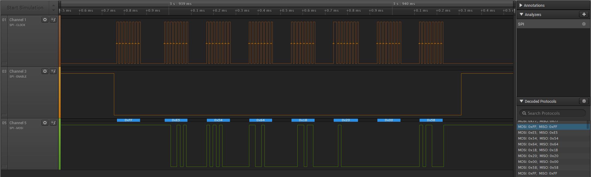
Now for the problem. I am trying to wrap my head around what they refer to as a shared miso-mosi pin. Admittedly I have searched the forum and did find a few posts, but I still don’t fully understand this concept. Based on the captures, CS goes low, the joystick sends in 1 byte(0xFF), receives 7 bytes back consisting of x-y-z-crc, then CS goes back to high.

From a software perspective, I am confused how I get 7 bytes back, if I only wrote 1 byte(0xFF).

  • Hello Burt,

    Typically for SPI, the Master (MSP430) has to send data out of MOSI in order to clock the slave (MLX90333). This is usually done with a "dummy" byte form the master when only data is needed from the slave. It is possible to send data to the slave while receiving data from the slave (aka full-duplex transmission), which is why the MOSI and MISO lines are usually separate. In this case, your end device only supports half-duplex communication and as a result, they reduced pin count by combining MOSI and MISO. Physically, you will have to tie these lines together (coming out of MSP430). This can be done with a diode, but a sufficiently large resistor does the trick as well (~10k). Software wise, you'll have to keep sending out dummy bytes from the MSP430 to clock additional data in. this should be either 0xFF or 0x00 depending on your physical connections. Basically, you do not want your dummy bytes to interfere or override the receiving bytes.
  • Thank you! I will give this a shot tonight.

**Attention** This is a public forum