This thread has been locked.

If you have a related question, please click the "Ask a related question" button in the top right corner. The newly created question will be automatically linked to this question.

CCS/MSP432P401R: Using the XDS110-ET Debug Probe With a Different Target throw error

Part Number: MSP432P401R

Tool/software: Code Composer Studio

Hi Team,

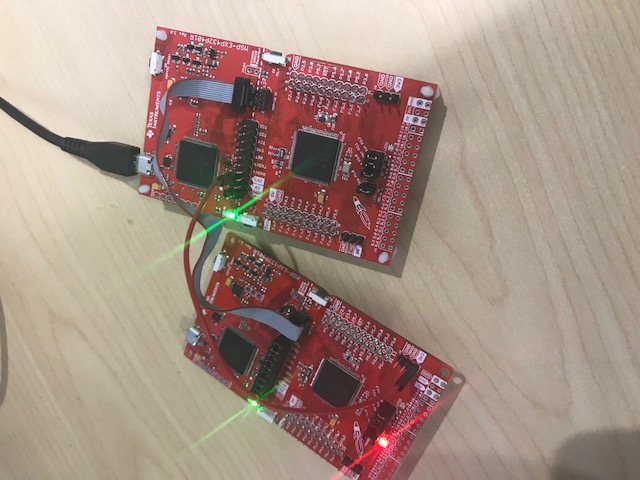
We have custom designed board that has MSP432 controller. I am trying to burn the code on this controller and debug it using the JTAG 10-pin connector.

Did follow the steps mentioned in the "MSP432P401R SimpleLink Microcontroller Launchpad Development kit" section 2.3.4 - Using the XDS110-ET Debug Probe With a Different Target.

However, whenever I try to debug the code the compiler throws the error mentioned below :

Error connecting to the target:
(Error -613 @ 0x0)
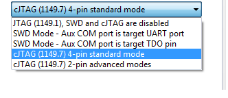
The target indicates that it is busy. Either try the SWD request
again, or abort the transaction.
(Emulation package 6.0.628.1)

Can someone please guide me about if there are any different steps apart from mention in the section 2.3.4? Are there any changes to be done in the Code Composer Studio?

Thank you in advance.

Vikram

  • Vikram,

    A few suggestions when using an external XDS110 from the LaunchPad:
    1. The JTAG cable does not provide power. You would need to make sure to power the custom dev board first.

    2. Review the VCC and also the Analog VCC pins to ensure they are connected

    3. Followed the recommended JTAG pins if they are properly connected.

    4. Did you enable JTAG protection?


    If none of the above helps, can you provide the following?
    A) Can you provide a picture of your setup?

    B) Can you go to View>Target Configurations>Click on "MSP432P401R.ccxml">click Target Configuration under Advanced Setup and navigate to Texas Instruments XDS110 USB Debug probe and give me your settings? I'm particularly interested in the JTAG/SWD/cJTAG mode setting but please include them all. A screenshot will suffice!

    C) Can you share the schematic capture for your custom board? You don't have to share everything but we could have a quick look and see if the JTAG and power are properly connected.

    These links below might be useful as well.
    software-dl.ti.com/.../ccsv7_debugging_jtag_connectivity_issues.html
    software-dl.ti.com/.../emu_xds_target_connection_guide.html
  • Thank you Evan for the response.

    --

    Evan Wakefield said:
    1. The JTAG cable does not provide power. You would need to make sure to power the custom dev board first.
    Yes the custom board is provided power and we cross verified the voltage on the Vcc pin which gives 3.3V

    Evan Wakefield said:
    Review the VCC and also the Analog VCC pins to ensure they are connected

    The Vcc pin is reviewed and it shows 3.3V. Not sure what you meant by Analog Vcc. Do you mean on the JTAG connector or on the MSP432 board?

    Evan Wakefield said:
    Followed the recommended JTAG pins if they are properly connected.

    The pin compatibility is confirmed between board the MSP432 board JTAG connector and the custom build board JTAG connector.

    Evan Wakefield said:
    Did you enable JTAG protection?

    Not sure how to enable JTAG protection. can you please guide?

    Evan Wakefield said:
    Can you provide a picture of your setup?

    Yes please find attached the picture of setup below.

    Settings in the MSP432P401R.ccxml is as below:

    Evan Wakefield said:
    Can you share the schematic capture for your custom board? You don't have to share everything but we could have a quick look and see if the JTAG and power are properly connected.

    Yes below is the connection and the area in red is the JTAG connection

    To add to the above points also we have removed all the jumpers on the J101 isolation block on the MSP432 ( The jumper connected in the picture is the GND which was also an experiment to check if it resolved the issue or not. But no luck)

    Secondly I had tried all 3 options in the Target configuration window for the JTAG/SWD/cTAG section.  Except the SWD mode I tried the other 3 options

    We are not sure what should we select in the "The JTAG TCLK Frequency" and "JTAG Signal isolation" option so we kept what was default.

    Hope this gives idea what is going wrong at my end to provide a solution.

    Vikram

  • Vikram,

    I have concerns around your schematic for your JTAG. If you do not put the pull up resistor (R4 found on the schematic for the Target Socket board users guide linked below on page 19) for the reset line, the device will always look like it is busy. Can you please make this adjustment as well as review the rest of your schematic? It seems you are missing it in the picture above.

    I would use the schematic attached to review the rest of your device layout as well. Make sure that you have the filter caps for VCORE and VCC. This is the best reference for laying out the MSP432 properly. As a note, many of the lines you see for JTAG in the referenced schematic in the link below has resistors on them. These resistors are current limiting resistors and are not required.
    www.ti.com/.../slau571
  • Hi Evan,

    Thank you for the information.

    I will go through the suggestions you have mentioned.

    But I see that the link that you have mentioned is related to MSP-TS432PZ100 Rev1.1 board whereas the board that I use is the MSP-EX432P401R. So will this change the suggestions that you have mentioned?

    Secondly I had also provided the screen shots for the Target Configuration. You did not comment on those. Is there anything that needs to be changed or configured in a different way in CCS.

    Thank you

    Vikram

  • Vikram,

    With regards to eithe rthe MSP-TS432PZ100 Rev 1.1, Rev 1.3 (which is a little further down on that same document I provided) or the MSP-EXP432P401R LaunchPad, the Reset line is treated the same. From the link below, see Figure 29 which shows the Reset connections below in the pic. Notice that Reset here also has a resistor pulling it up to 3v3 which you are missing in your schematic. If you do not have this, it likely won't matter what your debug target configuration settings are as the device will always respond as busy/ not accessible.

    The LaunchPad schematic: http://www.ti.com/lit/pdf/slau597

  • Thank you Evan.
    I will have to follow up with the hardware team in regards to why the pull up resistor was missed out.
    In terms of the Filter Caps that you had mentioned in earlier post for VCORE and VCC they are implemented just that the picture was not covering that part.

    Once the pull resistor concept is implemented I will re-test and get back to you.

    Regards,
    Vikram
  • Hi Evan,

    We have implemented the Pull Up resistor concept for the JTAG operation to work but still the error persist.
    The error shown are same as tomorrow.

    Vikram
  • Vikram,

    Can you walk me through a few details just to make sure we are on the same page.

    Were you careful to ensure that a 47K resistor was used?

    Did you try SWD (you mentioned earlier you did not as I understand your response)?

    Did you try going to Target Configuration > Test Connection to see if you receive anything?

    Do you have an extra launchpad to test to ensure your first launchpad emulator is good?

    And just to super double check,  you're sure your target is powered?

    My test set up for that is:

    J102 (XDS side) -> J101 (Target)

    3.3V on XDS side -> 3.3v on launchpad target side

  • Hi Evan,

    The resistor used was 20K and not 47K. Is it must to have 47K?
    We also tried using the SWD option but that too gave the error code 613
    Running the Test connection for both SWD and JTAG settings resulted success as per the message seen on screen.
    I will try and use another Lauchpad to confirm (XDS side not the Custom Board Side) to see if changes any outcome.
    The target board is powered up as we see the 3.3V across the Vcc pin.

    I tried to set up the same wasy as you did and guess what! The another launchpad got programmed over JTAG.
    Looks like something is missed on the Custom designed board.
    I will have to look into that.

    Thank you
    Vikram
  • Vikram,

    It may be the 20k resistor is not enough. Might test with a 47K resistor if you get the chance? Otherwise, I would cross-compare your schematic with the launchpad or target socket board schematic.
  • Vikram,

    Do you have any updates? if not, I may close this thread.
  • Hi Evan,

    We have yet not received the board from the contractor who is making the hardware design.

    I am waiting for the modified board with the resistor to be changed from 20K to 47K.

    Once I get it I will try to redo the execution and see how it goes.

    Can we have this thread open for next week?

    thank you

    Vikram

  • Thank you Evan the issue has been resolved.
    It was an issue on the actual custom board and the MSP432 itself had got damaged.
    Thank you for the suggestions.

    Vikram

**Attention** This is a public forum