This thread has been locked.

If you have a related question, please click the "Ask a related question" button in the top right corner. The newly created question will be automatically linked to this question.

CCS/MSP430F2619: How to enter into bootloader (BSL)

Part Number: MSP430F2619

Tool/software: Code Composer Studio

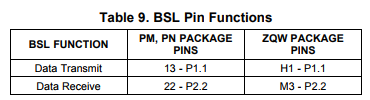
I was reading the SLAU319 to understand hardware requirement but confused with 2xx for MSP430F2619 because it has no TEST pin. The MSP430F2619 datasheet in BSL section only specify the UART P11 and P22 and that it. It did not note TEST or RST/MNI Pin. 

I have attached together the 

P35_UARTA0_RX to P22. (The UARTA0 only activated after 100mSec otherwise stay GIN as default POR)

P34_UARTA0_TX to P11. 

Would u think this work fine?

Not sure what else to attached hardware and how to activate entry?

R. 

  • Hello Richard,

    The MSP430F2619 has dedicated JTAG pins, so the BSL Entry Sequence should be applied to the !RST/NMI and TCK pins. See Section 1.3.2 and Figure 3 in the MSP430 Flash Device Bootloader (BSL) User's Guide for more details. Again, these pins are used to enter the BSL mode.

    Now, the pins in Table 9 in the datasheet are the BSL communication pins (transmit/receive). Thus, you'll need 4 pins in order to utilize the BSL function.

    Hopefully this makes sense.

    Regards,

    James

    MSP Customer Applications

  • Thank, I missed this figure 1.2.3, apologies :-)

    Can I have many TCK while the RST/NMI is LOW or has to be two exactly?

    It say BSL will not start if "There are fewer than two negative edges at TCK pin while RST/NMI ", does it imply allowance of more TCK of say 5 or 10 while RST/NMI stay LOW?

    I know it outside the scope of this datasheet, I designing hard logic to generate this waveform to enter BSL....
  • Hello Richard,

    richard payne said:
    Thank, I missed this figure 1.2.3, apologies :-)

    No apologies needed!

    richard payne said:
    Can I have many TCK while the RST/NMI is LOW or has to be two exactly?

    It say BSL will not start if "There are fewer than two negative edges at TC

    I would agree that the description does imply that more than two negative edges can occur at the TCK pin. It's important to keep the following two points in mind:

    • Pin states should last longer than 250ns before changing
    • !RST/NMI must transition from low to high while TCK is low (ideally in the middle of TCK's pin state)

    When you test this, please let me know if you're not able to enter the BSL mode. If you follow these guidelines, I don't expect you to encounter any issues.

    Regards,

    James

    MSP Customer Applications

  • For hardware development, we offer two target socket boards for the MSP430F2619.

    Regards,

    James

    MSP Customer Applications

**Attention** This is a public forum