This thread has been locked.

If you have a related question, please click the "Ask a related question" button in the top right corner. The newly created question will be automatically linked to this question.

MSP430G2553: Create a new segment in memory to use for read/write during calculations

Part Number: MSP430G2553

I have the code example msp430g2xx3_flashwrite_01.c running and understand most of it. I can't use the existing INFOA-D (64 bytes each) memory segments though, because I need a bigger area. So I tried creating new segments in the free space between INFOA where it ends (INFOA-D are mapped in reverse) and before 0xC000 where the next item (FLASH) begins. 

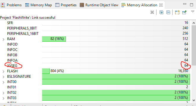
I tried a few different things and couldn't get any of them to work, so I made it real simple: declare a new segment the same size as INFOC (64 bytes) starting at 0x1100 and replace the SegC address location in msp430g2xx3_flashwrite_01.c with the 0x1100 address. It still doesn't work. Nothing else is different than the original working example, so it leads me to conclude that my new segment, which shows up under Memory Allocation if I select "show all", is not writable. Maybe I am just missing a setting for this? Has anyone successfully created new segments that they have written to? I could find a few examples of writing to flash in the forum but none that wrote to new segments.

Creating new segment in memory:

MEMORY
{
/* first we count up */
SFR : origin = 0x0000, length = 0x0010
PERIPHERALS_8BIT : origin = 0x0010, length = 0x00F0
PERIPHERALS_16BIT : origin = 0x0100, length = 0x0100
RAM : origin = 0x0200, length = 0x0200

/* then we count down. here in INFOC and INFOD Is where code example is working */
INFOA : origin = 0x10C0, length = 0x0040
INFOB : origin = 0x1080, length = 0x0040
INFOC : origin = 0x1040, length = 0x0040
INFOD : origin = 0x1000, length = 0x0040

/* here is my new stuff. From 0x1100 (end of INFOA) to 0xC000 (start of RAM) looks free */
XVSEG : origin = 0x1100, length = 0x0040

/* this is the original stuff */
FLASH : origin = 0xC000, length = 0x3FDE

/* okay, but now we are back to counting up? */
BSLSIGNATURE : origin = 0xFFDE, length = 0x0002, fill = 0xFFFF
INT00 : origin = 0xFFE0, length = 0x0002
INT01 : origin = 0xFFE2, length = 0x0002
INT02 : origin = 0xFFE4, length = 0x0002
INT03 : origin = 0xFFE6, length = 0x0002
INT04 : origin = 0xFFE8, length = 0x0002
INT05 : origin = 0xFFEA, length = 0x0002
INT06 : origin = 0xFFEC, length = 0x0002
INT07 : origin = 0xFFEE, length = 0x0002
INT08 : origin = 0xFFF0, length = 0x0002
INT09 : origin = 0xFFF2, length = 0x0002
INT10 : origin = 0xFFF4, length = 0x0002
INT11 : origin = 0xFFF6, length = 0x0002
INT12 : origin = 0xFFF8, length = 0x0002
INT13 : origin = 0xFFFA, length = 0x0002
INT14 : origin = 0xFFFC, length = 0x0002
RESET : origin = 0xFFFE, length = 0x0002
}

/****************************************************************************/
/* Specify the sections allocation into memory */
/****************************************************************************/

SECTIONS
{
.bss : {} > RAM /* Global & static vars */
.data : {} > RAM /* Global & static vars */
.TI.noinit : {} > RAM /* For #pragma noinit */
.sysmem : {} > RAM /* Dynamic memory allocation area */
.stack : {} > RAM (HIGH) /* Software system stack */

.text : {} > FLASH /* Code */
.cinit : {} > FLASH /* Initialization tables */
.const : {} > FLASH /* Constant data */
.bslsignature : {} > BSLSIGNATURE /* BSL Signature */
.cio : {} > RAM /* C I/O Buffer */

.pinit : {} > FLASH /* C++ Constructor tables */
.binit : {} > FLASH /* Boot-time Initialization tables */
.init_array : {} > FLASH /* C++ Constructor tables */
.mspabi.exidx : {} > FLASH /* C++ Constructor tables */
.mspabi.extab : {} > FLASH /* C++ Constructor tables */
#ifdef __TI_COMPILER_VERSION__
#if __TI_COMPILER_VERSION__ >= 15009000
#ifndef __LARGE_CODE_MODEL__
.TI.ramfunc : {} load=FLASH, run=RAM, table(BINIT)
#else
.TI.ramfunc : {} load=FLASH | FLASH2, run=RAM, table(BINIT)
#endif
#endif
#endif

.infoA : {} > INFOA /* MSP430 INFO FLASH Memory segments */
.infoB : {} > INFOB
.infoC : {} > INFOC
.infoD : {} > INFOD

.xvseg : {} > XVSEG

/* MSP430 Interrupt vectors */
TRAPINT : { * ( .int00 ) } > INT00 type = VECT_INIT
.int01 : {} > INT01
PORT1 : { * ( .int02 ) } > INT02 type = VECT_INIT
PORT2 : { * ( .int03 ) } > INT03 type = VECT_INIT
.int04 : {} > INT04
ADC10 : { * ( .int05 ) } > INT05 type = VECT_INIT
USCIAB0TX : { * ( .int06 ) } > INT06 type = VECT_INIT
USCIAB0RX : { * ( .int07 ) } > INT07 type = VECT_INIT
TIMER0_A1 : { * ( .int08 ) } > INT08 type = VECT_INIT
TIMER0_A0 : { * ( .int09 ) } > INT09 type = VECT_INIT
WDT : { * ( .int10 ) } > INT10 type = VECT_INIT
COMPARATORA : { * ( .int11 ) } > INT11 type = VECT_INIT
TIMER1_A1 : { * ( .int12 ) } > INT12 type = VECT_INIT
TIMER1_A0 : { * ( .int13 ) } > INT13 type = VECT_INIT
NMI : { * ( .int14 ) } > INT14 type = VECT_INIT
.reset : {} > RESET /* MSP430 Reset vector */
}

/****************************************************************************/

/****************************************************************************/

-l msp430g2553.cmd

Modified source code:

//******************************************************************************
// MSP430G2xx3 Demo - Flash In-System Programming, Copy SegC to SegD
//
// Description: This program first erases flash seg C, then it increments all
// values in seg C, then it erases seg D, then copies seg C to seg D.
// Assumed MCLK 771kHz - 1428kHz.
// //* Set Breakpoint on NOP in the Mainloop to avoid Stressing Flash *//
//
// MSP430G2xx3
// -----------------
// /|\| XIN|-
// | | |
// --|RST XOUT|-
// | |
//
// D. Dang
// Texas Instruments Inc.
// December 2010
// Built with CCS Version 4.2.0 and IAR Embedded Workbench Version: 5.10
//******************************************************************************

#include <msp430.h>

char value; // 8-bit value to write to segment A
volatile char myTemp = 0;

// Function prototypes
void write_SegC (char value);
char copy_C2D (void);

int main(void)
{

WDTCTL = WDTPW + WDTHOLD; // Stop watchdog timer
if (CALBC1_1MHZ==0xFF) // If calibration constant erased
{
while(1); // do not load, trap CPU!!
}
DCOCTL = 0; // Select lowest DCOx and MODx settings
BCSCTL1 = CALBC1_1MHZ; // Set DCO to 1MHz
DCOCTL = CALDCO_1MHZ;
FCTL2 = FWKEY + FSSEL0 + FN1; // MCLK/3 for Flash Timing Generator
value = 0; // initialize value

while(1) // Repeat forever
{
write_SegC(value++); // Write segment C, increment value
myTemp = copy_C2D(); // Copy segment C to D
__no_operation(); // SET BREAKPOINT HERE
}
}

void write_SegC (char value)
{
char *Flash_ptr; // Flash pointer
unsigned int i;

Flash_ptr = (char *) 0x1100; // Initialize Flash pointer
FCTL1 = FWKEY + ERASE; // Set Erase bit
FCTL3 = FWKEY; // Clear Lock bit
*Flash_ptr = 0; // Dummy write to erase Flash segment

FCTL1 = FWKEY + WRT; // Set WRT bit for write operation

for (i=0; i<64; i++)
{
*Flash_ptr++ = value; // Write value to flash
}

FCTL1 = FWKEY; // Clear WRT bit
FCTL3 = FWKEY + LOCK; // Set LOCK bit
}

char copy_C2D (void)
{
char *Flash_ptrC; // Segment C pointer
char *Flash_ptrD; // Segment D pointer
unsigned int i;
char temp;

Flash_ptrC = (char *) 0x1100; // Initialize Flash segment C pointer
Flash_ptrD = (char *) 0x1000; // Initialize Flash segment D pointer
FCTL1 = FWKEY + ERASE; // Set Erase bit
FCTL3 = FWKEY; // Clear Lock bit
*Flash_ptrD = 0; // Dummy write to erase Flash segment D
FCTL1 = FWKEY + WRT; // Set WRT bit for write operation

for (i=0; i<64; i++)
{
*Flash_ptrD++ = *Flash_ptrC++; // copy value segment C to segment D
}

temp = *Flash_ptrD--;

FCTL1 = FWKEY; // Clear WRT bit
FCTL3 = FWKEY + LOCK; // Set LOCK bit

return temp;
}

  • Perhaps I misunderstand your question, but so far as I know, there is nothing in the G2553 at 0x1100 other than possibly some part of the ROM-based BSL code that begins at 0x0C00.

    The G2553 has flash memory at INFOA-D and at 0xC000 - 0xFFFF, and nowhere else.  At least that's what the datasheet says.

  • You cannot use memory that does not exist. The linker command file just describes the hardware; telling the linker that there is some memory at a certain address does not create the transistors that implement the memory.

    If you want to have some new segment, you have to make some other segment smaller so that you have some actual memory where you can put it:

    XVSEG : origin = 0xC000, length = 0x0040
    
    FLASH : origin = 0xC040, length = 0x3F9E
    /*                   ^^               ^^ */
    /*                 higher        smaller */
  • Thanks, I see this now.

  • Thanks, I will shrink the FLASH and add the new piece I need to store my calculations. I actually have 255 doubles (that's why INFOA-D segments aren't enough already), so I will carve 1024 bytes off the front of FLASH to use for XVSEG. I read that writing to flash is very slow. Is there any advantage to creating 255 new segments of 4 bytes each vs 1 segment for all of them?
  • The flash segment size (i.e., what you must erase at once) is 512 byte. This is a property of the hardware; you cannot change it.
  • XVSEG : origin = 0xC000, length = 0x0400
    FLASH : origin = 0xC400, length = 0x3BFF

    If I map as above, I will have two 512 segments to write my calculations.

    One iteration of calculations would look like this
    1) set ERASE bit and erase first segment by writing zero to 0xC000; erase second segment by writing zero to 0xC200
    2) set unlock bit in order to write
    3) in a for loop i=0; i<255; i++, calculate 255 double values and write them to 0xC000 + i*4
    4) reset the lock
    5) add waits after the writes by checking for BUSY bit to be off

    Do you think this would work? It's different from the flash write example because I am keeping the memory unlocked while processor is doing other things (calculating values).
  • When your code is executed from flash, you do not need to wait for BUSY (see section 7.3.3 of the User's Guide).

  • I have successfully created a new memory segment of 1024 bytes to house my 255 doubles (with 4 bytes of free space).

    XVSEG : origin = 0xC000, length = 0x0400
    FLASH : origin = 0xC400, length = 0x3BDE

    Since it was pointed out by Clemens Ladisch that a segment is 512 bytes, I am erasing by writing a zero at both 0xc000 and 0xc200 before writing.

    I can write a value and read it back, but only one. I can't erase before the next write because I need to be able to use the previous value in the future. 

    I tried doing the erase and then unlocking for write and leaving it unlocked to do successive writes, but that didn't work. Nor did doing the erase and then unlocking and locking for > 1 write.

    Is this the way it is or is there something I can do to be able to write over and over again for one single erase? Attached is a stand alone test program to demonstrate the problem. I've scaled down NZEROS from 254 to 4, but problem is the same.

    /*
     * FIR_LPF_test.c
     * Test program uses new segment of FLASH from 0xc000 to 0xc3FF, inclusive
     * to hold interim calculations during Finte Impulse Response low pass filter.
     *
     * Change  lnk_msp430g2553.cmd to add new XVSEG and start FLASH later
     *  XVSEG   : origin = 0xC000, length = 0x0400
     *  FLASH   : origin = 0xC400, length = 0x3BDE
     *
     * Created on: Nov 14, 2017
     *      Author: Dayle Kotturi
     */
    #include <msp430.h>
    
    int numberOfErrors = 0;
    
    // These don't need to be global but visible in debugger this way
    double filteredData;
    int filteredIntData;
    int startTime, endTime, duration;
    unsigned char filteredLSB, filteredMSB, durationLSB, durationMSB;
    
    // For the filter
    //Low pass 40Hz
    #define START_ADDRESS_OF_XV_VALUES (0xC000)  // memory layout in: lnk_msp430g2553.cmd
    
    //#define NZEROS 254
    #define NZEROS 4
    #define GAIN   4.500036349e+00
    
    // Need to move xv from RAM .bss segment (capacity 512 B)
    // to FLASH segment located here:
    // We need to store 255 doubles or 255 * 4 bytes, so need 1020 bytes
    
    volatile double xv; // Instead of a big array, just declare one double.
               // This is what will be the gateway to write to and
               // read back from FLASH
    
    int iter = 0; // Used to count the first NZEROS iterations to avoid writing NaN to flash
    
    // Can fit the constants here
    #pragma DATA_SECTION (xcoeffs, ".const");
    #pragma DATA_ALIGN (xcoeffs, 4); // reserve 4 bytes for each value
    const float xcoeffs[] =
      { -0.0000085621, +0.0000000009, +0.0000089840, +0.0000114962,
        +0.0000067628, +0.0000009513, +0.0000009714, +0.0000072741,
        +0.0000130003, +0.0000106771, -0.0000000009, -0.0000112434,
        -0.0000144141, -0.0000084951, -0.0000011972, -0.0000012261,
        -0.0000091945, -0.0000164644, -0.0000135503, +0.0000000009,
        +0.0000143293, +0.0000184099, +0.0000108741, +0.0000015358,
        +0.0000015772, +0.0000118543, +0.0000212775, +0.0000175540,
        -0.0000000009, -0.0000186563, -0.0000240318, -0.0000142320,
        -0.0000020154, -0.0000020768, -0.0000156472, -0.0000281651,
        -0.0000233050, +0.0000000009, +0.0000249185, +0.0000321986,
        +0.0000191289, +0.0000027176, +0.0000028107, +0.0000212477,
        +0.0000383793, +0.0000318703, -0.0000000009, -0.0000343299,
        -0.0000445312, -0.0000265595, -0.0000037882, -0.0000039362,
        -0.0000298750, -0.0000541974, -0.0000452073, +0.0000000009,
        +0.0000491510, +0.0000640657, +0.0000384008, +0.0000055046,
        +0.0000057518, +0.0000438872, +0.0000800607, +0.0000671647,
        -0.0000000009, -0.0000739046, -0.0000969376, -0.0000584810,
        -0.0000084387, -0.0000088806, -0.0000682422, -0.0001254091,
        -0.0001060138, +0.0000000009, +0.0001185392, +0.0001568045,
        +0.0000954312, +0.0000138958, +0.0000147652, +0.0001145732,
        +0.0002127117, +0.0001817355, -0.0000000009, -0.0002078516,
        -0.0002782764, -0.0001715007, -0.0000253017, -0.0000272603,
        -0.0002145888, -0.0004044562, -0.0003510797, +0.0000000009,
        +0.0004155068, +0.0005666753, +0.0003561256, +0.0000536349,
        +0.0000590691, +0.0004758872, +0.0009193532, +0.0008192770,
        -0.0000000009, -0.0010276143, -0.0014473661, -0.0009416719,
        -0.0001472253, -0.0001688488, -0.0014214893, -0.0028811423,
        -0.0027061459, +0.0000000009, +0.0038348096, +0.0058012516,
        +0.0040895320, +0.0007001441, +0.0008908575, +0.0084578823,
        +0.0197449150, +0.0219689980, -0.0000000009, -0.0500579379,
        -0.1087319609, -0.1329096486, -0.0725347269, +0.1013352796,
        +0.3721470083, +0.6733017373, +0.9101442890, +0.9999999995,
        +0.9101442890, +0.6733017373, +0.3721470083, +0.1013352796,
        -0.0725347269, -0.1329096486, -0.1087319609, -0.0500579379,
        -0.0000000009, +0.0219689980, +0.0197449150, +0.0084578823,
        +0.0008908575, +0.0007001441, +0.0040895320, +0.0058012516,
        +0.0038348096, +0.0000000009, -0.0027061459, -0.0028811423,
        -0.0014214893, -0.0001688488, -0.0001472253, -0.0009416719,
        -0.0014473661, -0.0010276143, -0.0000000009, +0.0008192770,
        +0.0009193532, +0.0004758872, +0.0000590691, +0.0000536349,
        +0.0003561256, +0.0005666753, +0.0004155068, +0.0000000009,
        -0.0003510797, -0.0004044562, -0.0002145888, -0.0000272603,
        -0.0000253017, -0.0001715007, -0.0002782764, -0.0002078516,
        -0.0000000009, +0.0001817355, +0.0002127117, +0.0001145732,
        +0.0000147652, +0.0000138958, +0.0000954312, +0.0001568045,
        +0.0001185392, +0.0000000009, -0.0001060138, -0.0001254091,
        -0.0000682422, -0.0000088806, -0.0000084387, -0.0000584810,
        -0.0000969376, -0.0000739046, -0.0000000009, +0.0000671647,
        +0.0000800607, +0.0000438872, +0.0000057518, +0.0000055046,
        +0.0000384008, +0.0000640657, +0.0000491510, +0.0000000009,
        -0.0000452073, -0.0000541974, -0.0000298750, -0.0000039362,
        -0.0000037882, -0.0000265595, -0.0000445312, -0.0000343299,
        -0.0000000009, +0.0000318703, +0.0000383793, +0.0000212477,
        +0.0000028107, +0.0000027176, +0.0000191289, +0.0000321986,
        +0.0000249185, +0.0000000009, -0.0000233050, -0.0000281651,
        -0.0000156472, -0.0000020768, -0.0000020154, -0.0000142320,
        -0.0000240318, -0.0000186563, -0.0000000009, +0.0000175540,
        +0.0000212775, +0.0000118543, +0.0000015772, +0.0000015358,
        +0.0000108741, +0.0000184099, +0.0000143293, +0.0000000009,
        -0.0000135503, -0.0000164644, -0.0000091945, -0.0000012261,
        -0.0000011972, -0.0000084951, -0.0000144141, -0.0000112434,
        -0.0000000009, +0.0000106771, +0.0000130003, +0.0000072741,
        +0.0000009714, +0.0000009513, +0.0000067628, +0.0000114962,
        +0.0000089840, +0.0000000009, -0.0000085621,
      };
    
    void eraseSegment(unsigned int base_addr); // function prototype
    double highOrderLowPass(double input); // function prototype
    
    double noisyData[10] = {0.745544456622768,
                            0.745544456622768,
                            -0.755000000000000,
                            -2.29054445662277,
                            -2.30054445662277,
                            -0.785000000000001,
                            0.730544456622768,
                            0.715544456622768,
                            -0.794999999999999,
                            -2.30054445662277};
    
    int main(void)
    {
      WDTCTL = WDTPW + WDTHOLD; // Stop Watchdog Timer
    
      // Set up GPIO
      // This LED is used in stepwise debugging as another method to see that
      // events are occurring, eg. the USART RX interrupt.
      P1DIR |= BIT0;
      P1OUT &= ~BIT0; // Ensure that LED is OFF to begin
    
      // Use SMCLK
      DCOCTL = 0;                             // Select lowest DCOx and MODx settings
      BCSCTL1 = CALBC1_1MHZ;                  // Set DCOCLK to 1MHz
      DCOCTL = CALDCO_1MHZ;
    
      // Set up Timer1 A0 to time how long filtering takes.
      TA1CCTL0 = CM_1 + CAP; // rising edge capture mode, p. 372 Family;
      TA1CCR0 = 65535; // this value should never get reached - it would mean CPU was in LPM for ~2 seconds!
      TA1CTL = TASSEL_2 + MC_1 + ID_2; // SMCLK, up mode, divider=4 p.370 Family use for 512 Hz must use LPM 0
      TA1CCTL0 |= CCIE; // CCR0 interrupt enabled - do this last in the timer1 A0 setup
    
      eraseSegment(START_ADDRESS_OF_XV_VALUES);  // write a zero to the first byte of the segments to prepare for write
      eraseSegment(START_ADDRESS_OF_XV_VALUES+0x200);  // write a zero to the first byte of the segment to prepare for write
    
      FCTL3 = FWKEY;                            // Clear Lock bit - putting these two lines only here didn't work
      FCTL1 = FWKEY + WRT;                      // Set WRT bit for write operation
    
      int j;
      for (j=0; j<10; j++) {
    
        // Reset TA1R to zero counts
        TA1R = 0;
        // store starting time. Not really needed, but doing it as sanity check
        startTime = TA1R;
    
        // invoke the filter for this data point
        filteredData = highOrderLowPass(noisyData[j]);
    
        // store ending time
        endTime = TA1R;
    
        // update number of iterations. The first 254 contain zeros in the sample
        iter++;
    
        // calculate duration
        duration = endTime - startTime;
    
      }
      FCTL1 = FWKEY;                            // Clear WRT bit
      FCTL3 = FWKEY + LOCK;                     // Set Lock bit
    }
    
    // Timer1 A0 interrupt service routine
    //
    // Used to time how long it takes to filter one value.
    // This timer just counts and gets reset for each value.
    // Its max value is >> time needed for
    // one filtering. This way we don't have to worry about overflow.
    //
    // Main code just reads TAR before and after the filter operaion.
    // The difference is the duration.
    #pragma vector=TIMER1_A0_VECTOR
    __interrupt void TIMER1_A0_ISR (void)
    {
      //P1OUT ^= 0x01;          // only visible if stepping through in debug
      // Nothing to do here. We are just letting TA1R count.
      __no_operation(); // set breakpoint here to make sure
    }
    
    
    // FILTER CODE
    
    double readFlashValue(int i) {
        double *flash_ptr;
        flash_ptr = (double*) (START_ADDRESS_OF_XV_VALUES + i); // i is offset in units of doubles,
                                                                // because of the typecast
        return *flash_ptr;
    }
    
    void writeFlashValue(int i, double value) {
        double *flash_ptr;                        // Flash pointer for the write of double
    
        flash_ptr = (double *) (START_ADDRESS_OF_XV_VALUES + i);  // Initialize Flash pointer
    
        //FCTL3 = FWKEY;                            // Clear Lock bit
        //FCTL1 = FWKEY + WRT;                      // Set WRT bit for write operation
    
        *flash_ptr = value;                       // Write value to flash
    
        //FCTL1 = FWKEY;                            // Clear WRT bit
        //FCTL3 = FWKEY + LOCK;                     // Set Lock bit
        while((FCTL3 & BUSY));            //Wait until previous write completes
    }
    
    void eraseSegment(unsigned int base_addr) {
      char *Flash_ptr;                          // Flash pointer for the erase
    
      Flash_ptr = (char *) base_addr;           // Initialize Flash pointer
    
      FCTL1 = FWKEY + ERASE;                    // Set Erase bit
      FCTL3 = FWKEY;                            // Clear Lock bit
    
      *Flash_ptr = 0;                           // Dummy write to erase Flash segment
    
      FCTL1 = FWKEY;                            // Clear Erase bit
      FCTL3 = FWKEY + LOCK;                     // Set Lock bit
      while(FCTL3 & BUSY);              //Wait until erase is complete
    }
    
    double highOrderLowPass(double input)
    {
        volatile double next_xv;
        volatile double sum = 0.0;
        volatile double latest;
        int i,j;
    
        // First we age the values. This throws away
        // xv[0] and makes a free place at position, NZEROS
        for (i = 0; i < NZEROS; i++) {
    
            // For the first NZEROS iterations, there is nothing to read up to 'j', so set next_xv t0 0.
            // Not doing this, puts NaNs into flash and breaks the filter calculation
            j = NZEROS - i;
            if (j > iter) {
                next_xv = 0.;
            } else {
                next_xv = readFlashValue(i+1);
            }
            writeFlashValue(i, next_xv);
            __no_operation(); // use as breakpoint
        }
        // Then we write in the free place
        latest = input/GAIN;
        writeFlashValue(NZEROS, latest);
        __no_operation();
    
        for (i = 0; i <= NZEROS; i++) {
            next_xv = readFlashValue(i);
            sum = sum + (xcoeffs[i] * next_xv);
        __no_operation(); // use as breakpoint
        }
        return sum;
    }
    

  • Does it work if you unlock and enable writing around each write?
  • Yes, that works.

    I made some progress: first, I discovered this key sentence in section 7.3.3 of  the Family guide that answers my question:" A flash word (low and high bytes) must not be written more than twice between erasures. Otherwise, damage can occur. "

    So I thought what I am trying to do can't be done. But now I see another way that should work. Namely, if I use two 1024 segments (aka four 512 segments) and go back and forth writing to them alternately, I can erase once per write of all bytes. 

    So one iteration will be:

    1) erase segment A

    2) unlock for write

    3) copy segment B's values 2 through N to segment A at address: base+i, where i is increasing by 4 bytes because these are doubles

    4) compute new Nth value and write to segment A at the end of values written in (2)

    5) lock for write (only reading is needed now)

    6) do the data processing (summing and weighting of all N values) --- this only needs to read

    7) return result

    8) repeat over and over, switching between segment A and B and the source and destination

    The only downside is using 2048 bytes of FLASH for this. I'll report back how this goes. So far I feel pretty lucky that I haven't damaged my MSP430G2553 with multiple write attempts between erasures.

  • Does your code actually write to the same word more than once? Writing to different addresses should be no problem.
  • Yup, each iter, it writes over and over, because of the "aging" of the values. They get marched along the length of the array until they fall off the front, with a new value added at the end each time. I thought about making it like a circular buffer but even then, I need to write over and over, adding in the new value.

    Additional point, I found that, after erasing, there were NaN values in the segment, not zeros as I would have liked, so I had to write zeros in as well, in order not to break by sum when the array is still filling up. I.e. the first N iterations, the array is not full. One value is added each time (to the end), so it takes N iterations until there is a value in the front -- the oldest value having marched along to this first position. This is the "aging" I refer to above.
  • Flash erasing sets all bits to ones; flash writing (programming) sets some bits to zeros.

    You should implement some wear leveling algorithm, i.e., write the array index together with the actual value to the next free flash word, and when reading, search for the last valid (= not all ones) value.
  • re: Flash erasing sets all bits to ones; flash writing (programming) sets some bits to zeros.

    After the erase, I see NaN at the memory location.  See screenshot: "Flash is initially". I am writing zero to the base address of each 512 segment. Should I be writing 0xFF? I have seen code that does that for other MSP430 models but the flash write example for this model wrote a zero.

    Then, when I go through setting what I assign is a double of 4 bytes to 0., it works the first time (at address 0xC400, but the next time through, it sets 0.0 to BOTH 0xC404 and 0xC408. See attached screenshot FIR zeroing too early. This happens again for i=2, i=3.

    .

    Clemens Ladisch said:
    You should implement some wear leveling algorithm, i.e., write the array index together with the actual value to the next free flash word, and when reading, search for the last valid (= not all ones) value

    Why are you suggesting I go searching for the values? Can't I just use the address where I know it to be and then read that? Eg: 0xC400, 0xC404, 0xC408, ...? Are you saying it's not written at the address I give it? 

  • Writing 0xFF has no effect; it does not change anything from the erased value.

    After erasing, all bits are ones; for floating-point values, this is interpreted as NaN.

    The size of a double is eight bytes.

    When you are doing wear leveling, you do no longer know what value goes to which address. You write a newer version of the value to a different address (which is still erased), so when reading, you have to search for the latest version of this value.
  • Aha, I read this e2e.ti.com/.../237197 and from this thought double is 4 bytes, but sizeof() says 8! I'll switch to float to keep the same size segments.
  • Just to clarify, once you have erased a segment, you can enable Write, then write values to any or all of the addresses in that segment, sequentially or randomly, without fiddling with Write for each one. But as you say, you should only write to each location one time. Well, I suppose you could write 0xFFFF to a word more than once since that would have no effect, but it's best not to take the chance.
  • Thanks, yes, I am doing it this way. I.e. after the erase, only one unlock for write while writing the whole segment, then lock it. It's working well. I will mark it resolved after a bit more testing. Can you comment on the idea of waiting until the BUSY flag is cleared. Clemens said I didn't have to do this for FLASH, but other posts say it is necessary. 

  • Your code is executed from flash, so you do not need to wait for the BUSY bit (see sections 7.3.2.1 and 7.3.3.2 of the User's Guide).
  • Dayle Kotturi said:

    Thanks, yes, I am doing it this way. I.e. after the erase, only one unlock for write while writing the whole segment, then lock it. It's working well. I will mark it resolved after a bit more testing. Can you comment on the idea of waiting until the BUSY flag is cleared. Clemens said I didn't have to do this for FLASH, but other posts say it is necessary. 

    I've never waited for BUSY, so I don't think it's necessary.  I think it may be needed when writing from code in RAM, but if your code is in flash, or ROM for that matter, the processor won't come back to your next instruction until the write is finished.  And I'm pretty sure that BSL doesn't check BUSY either.

    By the way, you do have 512 bytes of RAM in this part.  You might need only a few bytes of that for a stack.  Would the remaining RAM be enough to hold your data while you process it?

  • Code is working without waiting for BUSY to clear, so thanks to Clemens and you for advice. RAM not an option because I have array of 255 floats for each calculation. 

**Attention** This is a public forum