This thread has been locked.

If you have a related question, please click the "Ask a related question" button in the top right corner. The newly created question will be automatically linked to this question.

Too much power consumption

Other Parts Discussed in Thread: MSP430F5437

We made small test board including msp430F5437.

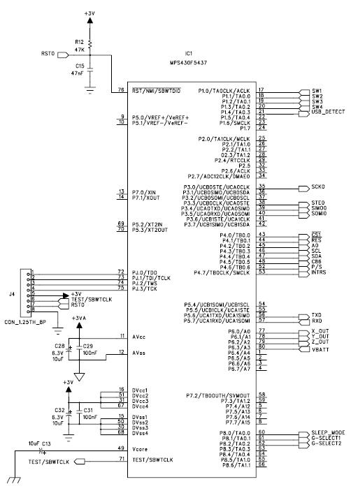
The board works fine but too much power is consumed.

Below is the schematic, and removing any peripherals, It takes more than 400 uA in LPM3.

The right side of MSP is all opened and left side is mounted.

The test code is LPM3 example code supplied by TI. (see the code below)

Could you tell me what is the problem of this circuit?


#include  "msp430x54x.h"


void main(void)

{

  WDTCTL = WDTPW + WDTHOLD;                 // Hold WDT

  UCSCTL4 = SELM_1 + SELS_1 + SELA_1;       // MCLK = SMCLK = ACLK = VLO


  P1OUT = 0x00;

  P2OUT = 0x00;

  P3OUT = 0x00;

  P4OUT = 0x00;

  P5OUT = 0x00;

  P6OUT = 0x00;

  P7OUT = 0x00;

  P8OUT = 0x00;

  P9OUT = 0x00;

  P10OUT = 0x00;

  P11OUT = 0x00;

  PJOUT = 0x00;


  P1DIR = 0xFF;

  P2DIR = 0xFF;

  P3DIR = 0xFF;

  P4DIR = 0xFF;

  P5DIR = 0xFF;

  P6DIR = 0xFF;

  P7DIR = 0xFF;

  P8DIR = 0xFF;

  P9DIR = 0xFF;

  P10DIR = 0xFF;

  P11DIR = 0xFF;

  PJDIR = 0xFF;


  __bis_SR_register(LPM3_bits);             // Enter LPM3

  __no_operation();

}

  • CoreMind,

    Could you also post a schematic of your measurement system showing where and how the current is being measured, and with what sort of equipment?  This will help to pinpoint all of the branches where the current might be flowing.

    Sparkchaser

  • Dear sparkchaser

    Thank you for your interest and reply.


    I measured current with two different method.

    At first I connected 100ohm resistance serially into the power cable, then measured voltage between each side of resistance with oscilloscope.

    Second, instead of resistance, Fluke 289 digital multimeter was used to measure current directly.

    The multimeter's accuracy is lower than 5%.


    The results from these two experiments shows similar results.


  • Electrolytic caps installed backwards can increase current consumption.

  • Also, don't forget that at high temperatures correctly installed caps cab be quite leaky, especially in the realm of LPM3.

  • Thank you for your interest and replies.


    The answer was outside of schematic I showed you.


    +3VA was not implemented so that AVcc and was not activated.

    The chip worked well but consumed more currents.


    I am really sorry for my mistakes.

    Best regards,

    Inbum Lee.


**Attention** This is a public forum