This thread has been locked.

If you have a related question, please click the "Ask a related question" button in the top right corner. The newly created question will be automatically linked to this question.

MSP430F6777: CPU not wake-up when Reset goes High

Part Number: MSP430F6777
Other Parts Discussed in Thread: TIDM-AUX-MODULE

Hi, all

We are using many MSP430F6777 for variable devices.

Now, we designed a new PCB for an environment that requests the robustness.

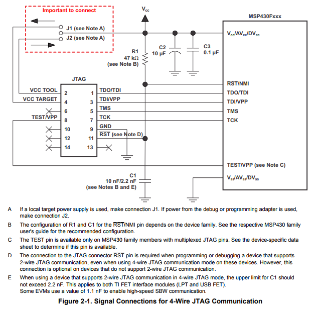
To establish the robustness, we attached a reset IC to protect MCU against the voltage drop.

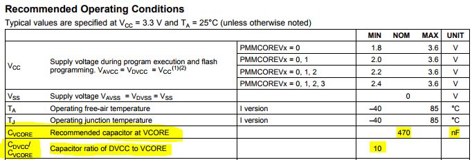
This system is working 3.3V Vcc and 25MHz DCO;

When the reset IC detects the voltage drop, the IC generates RST Low signal at 2.8V.

When the power is recovered, the reset signal will goes High about 200ms after.

We test the PCB under the instantaneous power failure conditions.

Usually this works good.

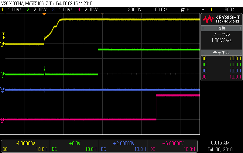
In this figure, the blue line means Vcc, the pink line means RST signal and the red signal means GPIO OUT signal.  GPIO OUT signal is generated to show the main program start like as follows.

#include <msp430.h>                

int main(void) {
    WDTCTL = WDTPW | WDTHOLD;        // Stop watchdog timer
    P1DIR = 0x01;                    // Set P1.0 to output direction
    P1OUT = 0x01;                    // Set P1.0 to High

After 100ms power failure, the reset IC generates 200ms RST signal then main program can start.

However sometimes the main program did not run and hang-up as follows;

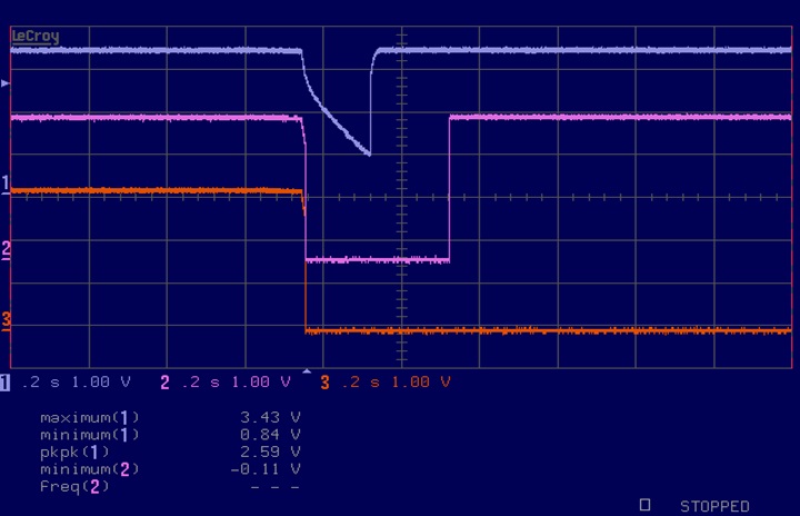
After many experiments, we can see following results.

1. Manual reset switch is available after hang-up.

2. Independent to clock speed.  Hang-up occurred when DCO=1MHz

3. Threshold voltage is about BOR voltage.

4. When Vcc goes zero, MCU always runs.

5. We tried with 3 boards and every boards have same manner.

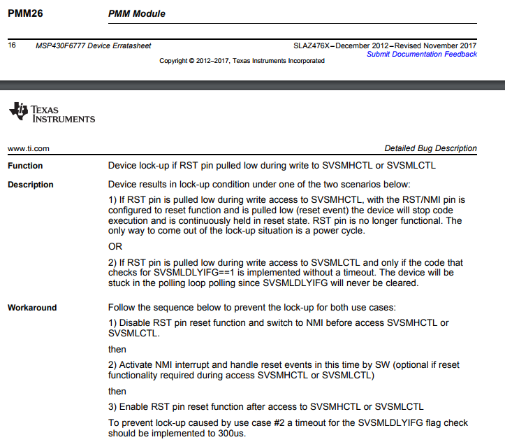
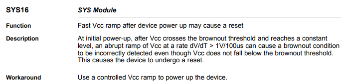
We want to know why the reset IC interferes the start-up.  Of cause we need workaround.

B. R.

Massa

  • Hello,

    Thank you for your post.

    I'm not sure you why you need an external reset IC since the MSP430F6777 already features an internal Power Management Module (PMM). Is the MSP430F6777 supplied by the same VCC as the reset IC? If so, I could see where this would be an issue, especially if the SVS/SVM in the PMM is also trying to control the device based on the VCC level.

    The PMM includes an integrated voltage regulator that supplies the core voltage to the device and contains programmable output levels to provide for power optimization. The PMM also includes supply voltage supervisor (SVS) and supply voltage monitoring (SVM) circuitry, as well as brownout protection. The brownout circuit is implemented to provide the proper internal reset signal to the device during power-on and power-off. The SVS/SVM circuitry detects if the supply voltage drops below a user-selectable level and supports both supply voltage supervision (the device is automatically reset) and supply voltage monitoring (the device is not automatically reset). SVS and SVM circuitry is available on the primary supply and core supply.

    Please check that you have all the recommended capacitors connected to the various pins of the MSP430F6777. For example, it's important for proper startup timing that the capacitance on DVCC is at least 10 times the capacitance on VCORE (recommended to be 470nF). I found the following table on page 59 in the datasheet.

    Also, are you using any of the auxiliary power supplies such as AUXVCC1, AUXVCC2, or AUXVCC3? If so, please keep in mind that the device starts whenever a supply is connected to DVCC or AUXVCC1. If both supplies are connected, AUX uses whichever voltage is higher to supply the digital and analog system voltages, VDSYS and VASYS. If the supplies (DVCC/AVCC and AUXVCC1) differ by less than 100 mV, the selected supply can be either DVCC/AVCC or AUXVCC1. The supply with the higher voltage is selected only if the difference is greater than 100 mV.

    I would highly recommend reading through the Auxiliary Supply System (AUX) Chapter 4 in the User's Guide. Also, please refer to the TIDM-AUX-MODULE TI Design as it's an excellent reference.

    Regards,

    James

    MSP Customer Applications

  • Thank you very much for  your kind advices, James.

    In this system, we use SVM to detect 1.91V core voltage.  And we use a discrete reset IC to detect voltage drop for system robustness.

    Okay, I checked the capacitors. Cvcore = 0.47uF and Cdvcc = 4.7uF.  They are recommended values.

    AUXVCC1 = AUXVCC2 = Vss = GND.

    AUXVCC3, DVCC and AVCC are connected to 3.3V power line.

    No battery power was used and just connected to power line.

    I think all conditions are there under the data sheet.  However sometimes hang-up.

    We want to know what was happened when reset signal was accepted for the system reliability.

    We are waiting technical reply.

    B.R.

    Massa

  • To confirm, you're only using SVML and disabling SVMH, SVSL, and SVSH? According to pages 105 to 106 in the User's Guide, the SVSH and SVMH modules are enabled by default and can be disabled by clearing the SVSHE and SVMHE bits, respectively, and the SVSL and SVML modules are enabled by default and can be disabled by clearing SVSLE and SVMLE bits, respectively.

    If VCORE falls below the SVML level, SVMLIFG (SVML interrupt flag) is set. If VCORE remains below the SVML level and software attempts to clear SVMLIFG, it is immediately set again by hardware. If the SVMLIE (SVML interrupt enable) bit is set when SVMLIFG gets set, an interrupt is generated. If a POR is desired when SVMLIFG is set, the SVML can be configured to do so by setting the SVMLVLRPE (SVML voltage level reached POR enable) bit while SVMLOVPE bit is cleared. If VCORE rises above the SVML level, the SVMLVLRIFG (SVML voltage level reached) interrupt flag is set. If SVMLVLRIE (SVML voltage level reached interrupt enable) is set when this occurs, an interrupt is also generated.

    Looking at your scope shots, I don't see much difference on the inputs, but something seems to be changing causing the issue to occur. For debugging purposes, it may be helpful to remove the reset IC to see exactly what the MSP430F6777 will do at various VCC levels.

    The following figure from the User's Guide shows when the various SVS and SVM interrupts get triggered at various levels of DVCC. Can you try monitoring SVMLIFG and perhaps any other ones you've enabled?

    According to page 113 in the User's Guide, the state of SVMLIFG, SVMLVLRIFG, SVMHIFG, and SVMLVLRIFG can be monitored on the external SVMOUT pin. Each of these interrupt flags can be enabled (SVMLOE, SVMLVLROE, SVMHOE, SVMLVLROE) to generate an output signal. The polarity of the output is selected by the SVMOUTPOL bit. If SVMOUTPOL is set, the output is set to 1 if an enabled interrupt flag is set. I would record these with and without the reset IC as a comparison.

    Regards,

    James

    MSP Customer Applications

  • Hi, James,

    Thanks for your reply.  Your reply always encourage us.

    Now, we try to run with very simple program.  Just stop the watchdog timer and disable the SVS.

    Program is as follws:

    void main( void )
    {
       // WDT Hold
       WDTCTL = WDTPW | WDTHOLD;

       // SVS,SVM Disable
       PMMCTL0_H = PMMPW_H ;                // PMM unlock
       SVSMHCTL &= ~( SVSHE | SVMHE ) ;     // SVSH,SVMH Disable
       SVSMLCTL &= ~( SVSLE | SVMLE ) ;     // SVSL,SVML Disable
       PMMCTL0_H = 0x00 ;                   // PMM lock

       //LED ON
       P3DIR = BIT05 ;                      // OUTPUT
       P3OUT = BIT05 ;                      // LED ON

       for(;;)  {
       }
    }

    However, while our power off/on tests, sometimes wake-up failure occurred.

    This failure may not be associated to SVS/SVM module.

    Wait for your reply.

    B.R.

    Massa.

  • Hello Massa,

    Thank you for the additional details. I spent some time going through the erratasheet, and I found two errata that could be causing the issue here.

    First, PMM26 may be happening, but it depends on how the SVSL or SVML is configured. I'm not sure if the issue that you're observing is caused before the SVSL or SVML are disabled. The function and description sounds similar to what you're seeing.

    More importantly, SYS16 is related to a fast VCC ramp that causes a reset. In your scopeshots, the VCC does seem to ramp up quickly.

    I could have missed an errata that's causing the issue, so please feel free to look through the erratasheet.

    Regards,

    James

    MSP Customer Applications

  • Thank you James.
    Reset IC generates RST signal, then all MSP430 registers are reset.
    As default values, SVS starts to check internal voltages even if reset signal is generated.
    Then the errata PMM26 makes MSP430 Lock-up.
    In this reason, we can explain our phenomena. Thank you very much.
    Now, we confirm PMM26 problem on our PCB and will talk together to find workaround.

    B.R.
    Massa
  • Hello Massa,

    This is great news! Nice debugging work. Please let me know if you have any further questions.

    Regards,

    James

    MSP Customer Applications
  • Hello James,
    Nice to see you.
    The errata PMM26 describes if reset signal is occurred just when program code is writing data to SVSMHCTL.
    However our software never write SVSMHCTL after initializing ports.
    I supposed the reset signal caused to write default value to SVSMHCTL and this made the errata PMM26 lock-up.
    We tried to make power failure with all default values in all SVS registers. I guess no writing must be occurred when reset.
    However, we could find lock-up! Almost same as common software!
    Our lock-up phenomena may not be associated to SVSMHCTL, and the workaround is useless.
    We need more information about the relation between reset signal and lock-up MCU.

    B.R.
    Massa.
  • Hello Massa,

    Unfortunately, this is not an easy issue to debug, so let's start back at the beginning with some simple tests.

    First, program the MSP430F6777 with very simple code (such as below).

    #include <msp430.h>
    void main(void)
    {
        WDTCTL = WDTPW | WDTHOLD;               // Stop WDT
        
        P3DIR = BIT5;
        P3OUT = BIT5;
    
        while(1);
    }

    Next, isolate the MSP430F6777 from the reset IC and turn VCC on/off/on. Does the lock-up still occur? If not, we'll continue.

    Regards,

    James

    MSP Customer Applications

  • Hello James,

    Thanks for your reply.
    We try to run with two programs.

    First one is very simple program.  Just stop the WDT.
    And next, we set the reset pin to NMI and disable SVS/SVM then RST enabled. This sequence is following on the workaround of PMM26.
    We try to check the behaviors with and without the reset IC.

    Results are as follows:

    Mount Reset IC Remove Reset IC
    Simple Default Setting Lock-up occurred Okay to run
    Disabled SVS/SVM Lock-up occurred Okay to run

    This results show we never use the reset IC to watch the power voltage! And PMM26 is not related to this lock-up.

    If the reset signal makes lock-up, it seems so curious.  We want to know what is happened in this chip when MSP accepts reset signal.

    Regards,

    Massa.

  • Hello Massa,

    This is a good start, especially if the lock-up is repeatable. With the reset IC removed, can you take scope shots with the VCC points (steady, lowest point, etc.) labeled and also the GPIO output?

    Honestly, I'm concerned about how fast VCC is rising after it's turned back on during your test (see your first two screenshots). I find it very, very strange that those scope shots are basically identical but one is fine and the other is lock-up. Is there a way that you can slow down that sharp rise on VCC?

    Earlier, you confirmed that AUXVCC1 and AUXVCC2 are connected to DVSS which is as recommended, but they should also be disabled in the software by setting AUXxMD = 1 and AUXxOK = 0.

    Also, the pair of pins VDSYS1 and VDSYS2, VASYS1 and VASYS2 must be connected externally on board for proper device operation. The LCDCAP/R33 pin must be connected to DVSS if it is not used. Can you confirm this?

    What's the part number of your reset IC?

    Regards,

    James

    MSP Customer Applications
  • Hello Massa,

    Can you monitor the TEST/SBWTCK pin when you see the lock-up? I suspect that there's noise on this line causing the lock-up to occur. The snippet below is from the MSP430 Programming With the JTAG Interface User's Guide.

    On the other hand, this could sometime avoid the device to execute the application correctly after reset. Some practical experiences show that by adding an external pull-down resistor (e.g. 4.7 kOhm) at the TEST/SBWTCK pin will help to eliminate this problem.

    Also, I'd recommend adding an external 47kOhm pull-up resistor to VCC and a pull-down capacitor to GND to the RST line. I'm not sure what JTAG interface you're using, but see the recommended circuits for both 4-wire JTAG and 2-wire SBW (taken from the MSP430 Hardware Tools User's Guide).

    Regards,

    James

    MSP Customer Applications

  • Hello, James

    Of cause we observed TEST pin when the lock-up occurred with an oscilloscope.
    At first, we assumed the CPU went into the BSL mode and observed TEST pin.
    TEST pin was opened and pull down to Vss internally. We could not find any pulse or signal on TEST pin.

    Regards,
    Massa
  • Hello, James.

    1. Without reset IC, the output signal from GPIO becomes High with same figure but rise up soon.
    2. Power and MCU are configured as one equipment and difficult to change the power supply now. We will try it.
    3. In the test program, AUXxMD have a default value and not changed. I will confirm we set AUXxMD in system software.
    4. We confirmed VDSYS1 and VDSYS2, VASYS1 and VASYS2 were connected like as PZ100B. And LCDCAP/R33 was connected to DVss.
    5. Reset IC is BD45272G by ROHM Semiconductor.

    regards,
    Massa.
  • Hello Massa,

    Thanks so much for providing feedback - it's very helpful. For the BD45272G reset IC, the ROHM datasheet shows that this device is the open drain output type which is good. Also, I see in the typical application diagram (shown below) in the ROHM datasheet that they show the external pull-down capacitor (we recommend 1nF) and external pull-up resistor (we recommend 47kOhm). It sounds like you're going to try adding these, so let's hope adding them resolves the issue.

    Regards,

    James

    MSP Customer Applications

  • Hello James.

    Thanks for your suggestion.  However we have enough capacitors and no noise signal was observed.

    I will show our current circuit as follows:

    Regards,

    Massa.

  • Hello James.
    We had some experiments with default values(AUX1MD=AUX2MD=0) and AUX1MD=AUX2MD=1, AUX1OK=AUX2OK=0.
    Then we can confirm the lock-up issues in both setting.
    The setting to AUXxMD is not related to the issue.

    Regards,
    Massa.
  • Hello Massa,

    Thanks for confirming and providing the schematic snippet. Even though it didn't make a difference, let's keep the recommended AUXxMD = 1 and AUXxOK = 0 settings in your code.

    I was looking through the ROHM datasheet and noticed that in the Operational Notes section, they recommend putting a 1uF capacitor between VDD and GND of the reset IC. Could you try replacing C74 with a 1uF capacitor?

    Next, it'd be very helpful to get detailed scope shots (VDD, RST, GPIO) that have specific voltages and time intervals clearly labeled (something like Figure 17 in the ROHM datasheet shown below). I know you provided two in your initial post, but they are hard to know levels, slopes, time intervals, etc.

    Do you know if the MSP430 is sourcing power to any peripheral devices using the GPIOs? Are DVCC and AVCC powered by the same source?

    Regards,

    James

    MSP Customer Applications

  • Hello Massa,

    Have you had a chance to review my latest feedback?

    Regards,

    James

    MSP Customer Applications
  • Hello James,

    Thanks for your detailed reply.

    And it's okay to keep the recommended settings.

    In the schematic I showed several days ago, BD45272G Vdd have only 0.1uF capacitor.

    However the power line provides  4.7uF bypass capacitor close to C74.  I think it's enough to prevent the voltage drop in the power line.

    The circuit of power supply is very simple. A LDO LP2985A-33 provides 3.3V for DVcc and AVcc.

    I will show the power supply as :

    Now we can not find any short pulse on Reset line with faster scanning.  If the faster scope shots may be helpful, I will request to catch pictures to our hardware team when the reset signal will rise and fall.

    Regards,

    Massa.

  • Hello James,

    We want to see this issue is associate with the errata PMM26.

    We can suppose two stories about Description 1).  Please teach me which is correct.

    1. While a program code access to SVSMHCTL to change the value, the reset event is occurred by RST goes Low then lock-up.

    2. While the RST signal becomes Low, the power supply voltage changes cause BOR event then lock-up.

    I think RST signal can make BOR and POR events, and when RST keeps low MSP430 keeps BOR and POR status.

    Figure 1-1 BOR/POR/PUC in User's Guide shows brown reset circuit and RST signal is same level for BOR and POR.

    Then BOR and POR keep reset state while RST=Lo, and voltage down signal from brownout reset and SVS can not make any effect.

    Am I Correct or Wrong?

    If RST input can keep BOR and POR status, I will decide this issue is not associate to PMM26.

    Please teach me the phenomena while RST=Lo.

    Regards,

    Massa.

  • Hello Massa,

    I'm looking deeper into this. In the meantime, can you confirm how long the Reset and MSP430F6777 devices have been powered up before seeing this issue? In the screenshots attached in your first post, it appears that they both had been powered on for some time before dropping VCC and observing the issue. We need to know if the issue occurs right after powering the devices up or after they've been powered up for a while or both.

    If you could provide more detailed scope shots that show when the issue happens or doesn't happen, it would be helpful. Things like startup, slope rates, time intervals, and voltage levels would be helpful. I can try to replicate the issue here, but it may be not be possible.

    Regards,

    James

    MSP Customer Applications
  • Hello James,

    We got some pictures when MSP430F6777 was powered on.

    In all pictures, Ch1: Power, Ch2: Output of Reset IC, Ch3: TEST pin, Ch4: LED signal.

    1. When power on:

    2. Short time power down - succeeded 1

    3. Short time power down - succeeded 2

    4. Short time power down - failed 1

    5. Short time power down - failed 2

    6. Then I found the difference between the case of succeeded and failed.  I will show next picture:

    When reset is okay and standard power on, we can not find the figure of voltage overshoot on Vcc.  However when reset is fail and lock-up, we find the figure of voltage overshoot.

    It seems that: In normal case MSP430 use enough current and power drop is occurred the no overshoot is found.  And in lock-up case, MSP430 can not use enough current in the internal circuits and less power is used then we can find overshoot figure.

    This is my consideration.  But I don't know what is happened in MSP430.

    I hope this experiments help you to understand the issue of lock-up.

    Regards,

    Massa.

  • James, Massa,

    sorry for late reply from my site was fully occupied the last 2 weeks.
    The scope shots are very help and point me to AUXPMM2 ERRATA

    Can you please measure the current consumption of the device in fail mode to check if we are in Latch-Up situation means several mAs?
    And then zoom into the rising edge on VCC what is the slew rate would it match the AUXPMM2?

    If you end up in this scenario pls follow the workaround and limit the rise time by a current limiting element e.g. resistor.

  • Hello Walther,

    Thank you for your reply.

    This errata is very interesting, but now it's very difficult to insert a register between the power supply and Vcc of MSP430.

    We must consider how to slow down the rise-up time of the power supply.

    I think SVS and AUX are working asynchronously from the reset signal, and SVS, AUX, System reset, RST IC and power supply work simultaneously.

    Oh, very complicated!!!

    Now, I have two questions:

    1. Why lock-up issue was not appeared when the reset IC was removed?

    2. When latch-up current is occurred, external RST signal(Hi->Lo->Hi) can reset system?

    We can go forward to resolve this issue obviously.  Please help us or give us some hints in last miles.

    Regards,

    Massa

  • Hi Massa,

    not sure what you mean with inserting a register, simply measure the current of the MSP or the whole application, if you see several mA increase you are affected by AUXPMM2.

    As described in the ERRATA only a power cylce will remove this condition.

    Can you give a bit more details what you mean with your first question? "Why lock-up issue was not appeared when the reset IC was removed?"

    So does this mean you replaced an external supersvisor circuit connected to RST pin by a RC circuit?

  • Hello Massa,

    Can you please provide detailed scope shots like the ones above without using the reset IC, so we can compare them? I suspect that there's no overshoot condition when the reset IC is NOT used. Please confirm.

    Massa1 said:

    This errata is very interesting, but now it's very difficult to insert a register between the power supply and Vcc of MSP430.

    We must consider how to slow down the rise-up time of the power supply.

    A resistor in series will do this.

    Regards,

    James

    MSP Customer Applications

  • Hello, Walther
    Thank you for your suggestion.
    We don't use a battery or another auxiliary power supply.
    DVcc, AVcc and AUXVCC3 are connected to single power supply.
    AUXVCC1 and AUXVCC2 are connected to GND.
    In this case, is the Errata AUXPMM2 effective?
    We are using a reset IC to detect power down.
    The IC is connected to RST pin and pull down to Low while VCC is dropped less than 3V.

    Regards,
    Massa.
  • Hello, James
    In our circuit, it's so difficult to insert a register to power supply.
    And we are concerned the effect of the register to drop power supply voltage.
    Now, we are employed a new reset IC to check MSP430 is active, and if not active, the IC generate reset signal again.
    I observe the new circuit works good.
    If we can get an information the reset IC always works good when MSP430 can not run with voltage down from TI, we want to close this issue.
    Regards,
    Massa
  • Hello,

    Massa1 said:
    In our circuit, it's so difficult to insert a register to power supply.
    And we are concerned the effect of the register to drop power supply voltage.

    I believe you mean "resistor" here instead of "register". If the existing layout/board has been finalized, I can understand that there would not be a dedicated place/pads for populating a resistor. However, our recommendation of inserting an resistor between the supply and VCC pins is merely an attempt to find a fix to the issue. If the resistor is several Ohms (~10 to 20Ohm), then it will not drop much voltage at the low currents consumed by the MSP430. For testing purposes, you could add the resistor using small wires, etc.

    Massa1 said:
    Now, we are employed a new reset IC to check MSP430 is active, and if not active, the IC generate reset signal again.
    I observe the new circuit works good.

    What's the part number of this new reset IC? Is the reset still controlled by an open drain output or push-pull? Also, I suspect that with the new reset IC, the MSP430 is not seeing that sharp spike (but instead seeing a smooth roll-off) that existed when the MSP430 would lock up. As Dietmar mentioned, adding a resistor should help eliminate that sharp voltage spike. By active, I assume that the new reset IC is checking the GPIO indicating that the device has started up and will keep triggering the reset pin of the MSP430 until it starts. Is that correct?

    Massa1 said:
    If we can get an information the reset IC always works good when MSP430 can not run with voltage down from TI, we want to close this issue.

    Unfortunately, I'm not sure what you mean here.

    Regards,

    James

    MSP Customer Applications

  • Hello,

    Massa1 said:
    We don't use a battery or another auxiliary power supply.
    DVcc, AVcc and AUXVCC3 are connected to single power supply.
    AUXVCC1 and AUXVCC2 are connected to GND.
    In this case, is the Errata AUXPMM2 effective?

    Please keep in mind that the AUXPMM module is still getting used here, even though you're not using the AUXVCC1 or AUXVCC2 in your application. In Scenario 2 of AUXPMM2 errata, it specifically mentions that latch-up current can appear if rise times seen by the AUXPMM module are in the range of 140kV/s (faster rise times increase probability) and can only be reset by a power cycle. I understand that the description mentions a battery but that's because they have a low internal resistance - please keep in mind that other power supplies can also introduce fast rise times, which should be the focus instead.

    As Walther pointed out earlier, you can perform a simple test of measuring the latch-up current. If it's several mA and the rise time is close to 140kV/s, I would suspect that this is the AUXPMM2 errata. We've recommended adding a current-limiting resistor as mentioned in the workaround, but it doesn't seem like you've tried this yet. Thus, I'm not sure how much more I can help here.

    It sounds like the different reset IC has fixed your issue, which is good to hear.

    Regards,

    James

    MSP Customer Applications

**Attention** This is a public forum