Part Number: MSP432P401R
Tool/software: Code Composer Studio
I have an unusual problem, after I initialize the clock frequency for my uC, it will randomly enter the ISRFault loop or NmiSR. I'm using an exemple of program for a e-ink pervasive display, but I can't test anything cause after I do the init for the microcontroller, I get this faulty interrupt and can't understand the why.
#include "conf_EPD.h"


/* Glossary of Acronyms
 * GU = Global Update
 * PU = Partial Update
 * LUT = Look-up table, the array to define the parameters of driving waveform
 * OTP = One Time Programming, the LUTs are pre-programmed in driver IC
 */

/**
 * \brief define the timing controller type and size of EPD
 * \note
 *  - eTC=external timing controller (driver IC)
 *  - iTC=internal timing controller */
// eTC
#define sz_eTC_144  0 //J7 Switches 0000 001x
#define sz_eTC_190  1 //J7 Switches 0000 000x
#define sz_eTC_200  2 //J7 Switches 0000 001x
#define sz_eTC_260  3 //J7 Switches 0000 000x
#define sz_eTC_271  4 //J7 Switches 0000 000x
// iTC
#define sz_iTC_215  5 //J7 Switches 1010 000x
#define sz_iTC_287  6 //J7 Switches 0101 010x
#define sz_iTC_420  7 //J7 Switches 0101 010x

/**
 * \brief define the EPD drivers with film material
 * \note
 *  - BW=black and white colors, Aurora film
 *  - BWR=black, white and red colors, Spectra-red film
 *  - a=Aurora Ma (V230)
 *  - b=Aurora Mb (V231) */
#define dr_eTC_BWa          0
#define dr_eTC_BWb          1
#define dr_iTC_BWb          2

/**
 * \brief Configure the following two definitions by your connected display model  */
#define USE_EPD_Type    dr_eTC_BWb
#define USE_EPD_Size    sz_eTC_190


#if (USE_EPD_Type==dr_eTC_BWa || USE_EPD_Type==dr_eTC_BWb)
    #if(USE_EPD_Type==dr_eTC_BWa)
        #define  EPD_Type       dr_eTC_G2_Aurora_Ma
    #else
        #define  EPD_Type       dr_eTC_G2_Aurora_Mb
    #endif
    #if(USE_EPD_Size==sz_eTC_144)
        extern unsigned char const  Image_eTC_144_01[];
        extern unsigned char const  Image_eTC_144_02[];
        #define  EPD_Size     EPD_144_BW
        #define Image1        (uint8_t *)&Image_eTC_144_01
        #define Image2        (uint8_t *)&Image_eTC_144_02
    #elif(USE_EPD_Size==sz_eTC_190)
        extern unsigned char const  Image_eTC_190_01[];
        extern unsigned char const  Image_eTC_190_02[];
        #define  EPD_Size     EPD_190_BW
        #define Image1        (uint8_t *)&Image_eTC_190_01
        #define Image2        (uint8_t *)&Image_eTC_190_02
    #elif(USE_EPD_Size==sz_eTC_200)
        extern unsigned char const  Image_eTC_200_01[];
        extern unsigned char const  Image_eTC_200_02[];
        #define  EPD_Size     EPD_200_BW
        #define Image1        (uint8_t *)&Image_eTC_200_01
        #define Image2        (uint8_t *)&Image_eTC_200_02
    #elif(USE_EPD_Size==sz_eTC_260)
        extern unsigned char const  Image_eTC_260_01[];
        extern unsigned char const  Image_eTC_260_02[];
        #define  EPD_Size     EPD_260_BW
        #define Image1        (uint8_t *)&Image_eTC_260_01
        #define Image2        (uint8_t *)&Image_eTC_260_02
    #elif(USE_EPD_Size==sz_eTC_271)
        extern unsigned char const  Image_eTC_271_01[];
        extern unsigned char const  Image_eTC_271_02[];
        #define  EPD_Size     EPD_271_BW
        #define Image1        (uint8_t *)&Image_eTC_271_01
        #define Image2        (uint8_t *)&Image_eTC_271_02
    #endif

 #elif(USE_EPD_Type==dr_iTC_BWb)
    #if(USE_EPD_Size==sz_iTC_215)
        extern unsigned char const  Image_iTC_215_01[];
        extern unsigned char const  Image_iTC_215_02[];
        #define  EPD_Type     dr_iTC_215_Aurora_Mb
        #define  EPD_Size     EPD_215_BW
        #define Image1        (uint8_t *)&Image_iTC_215_01
        #define Image2        (uint8_t *)&Image_iTC_215_02
    #elif(USE_EPD_Size==sz_iTC_287)
        extern unsigned char const  Image_iTC_287_01[];
        extern unsigned char const  Image_iTC_287_02[];
        #define  EPD_Type     dr_iTC_287_Aurora_Mb
        #define  EPD_Size     EPD_287_BW
        #define Image1        (uint8_t *)&Image_iTC_287_01
        #define Image2        (uint8_t *)&Image_iTC_287_02
    #elif(USE_EPD_Size==sz_iTC_420)
        extern unsigned char const  Image_iTC_420_01[];
        extern unsigned char const  Image_iTC_420_02[];
        #define  EPD_Type     dr_iTC_420_Aurora_Mb
        #define  EPD_Size     EPD_420_BW
        #define Image1        (uint8_t *)&Image_iTC_420_01
        #define Image2        (uint8_t *)&Image_iTC_420_02
    #endif
#endif

void main(void)
{
    system_init();
    EPD_display_init();
    Systick_Configuration();
    //EPD_delay_ms(1000);
    Set_AssignEPD_Drive(EPD_Type,EPD_Size,USE_Temperature_Sensor);
    //EPD_display_GU_from_pointer(Image2,Image1,GU_Mode,true);

    __delay_cycles(200000);
    while(true)
    {
        EPD_display_GU_from_pointer(Image2,Image1,GU_Mode,true);
        EPD_delay_ms(5000);
        EPD_display_GU_from_pointer(Image1,Image2,GU_Mode,true);
        EPD_delay_ms(5000);
    }
}
void system_init(void)
{
/* Halting the Watchdog */
MAP_WDT_A_holdTimer();
/* Enabling FPU for DCO Frequency calculation */
MAP_FPU_enableModule();
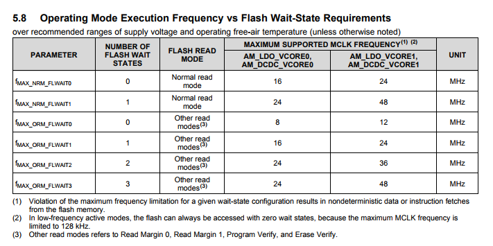
/* Setting DCO to 48MHz (upping Vcore) */
MAP_PCM_setCoreVoltageLevel(PCM_VCORE1);
/* Setting the DCO Frequency to a non-standard 48MHz */
//MAP_CS_setDCOFrequency(48000000);
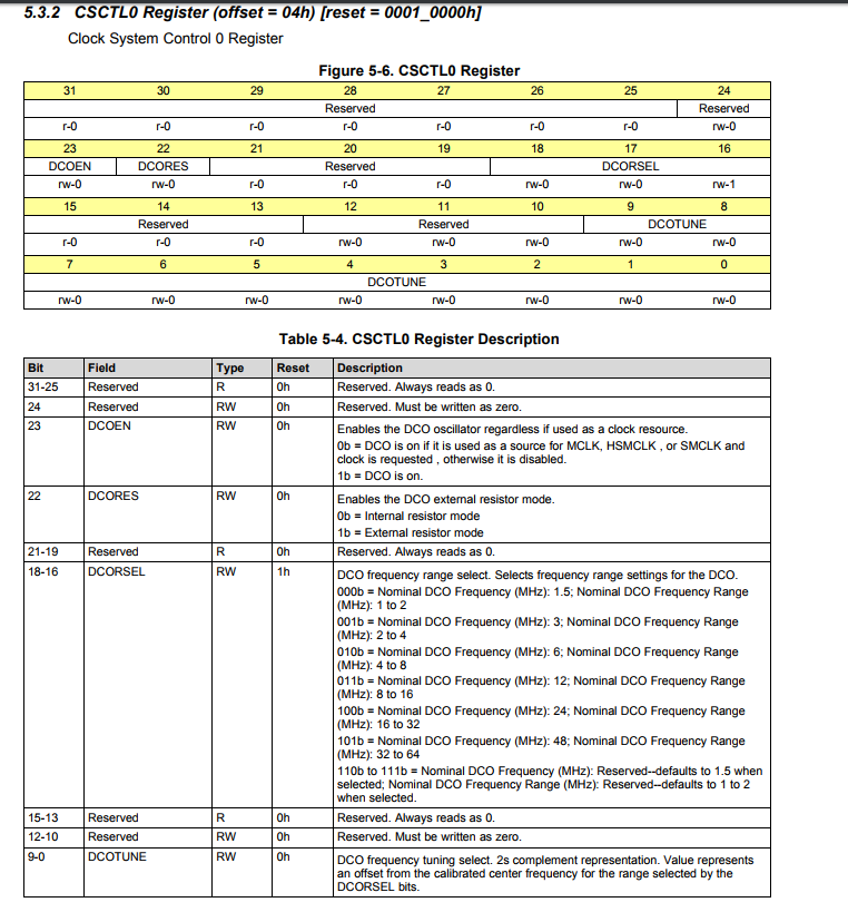
CS_setDCOCenteredFrequency(CS_DCO_FREQUENCY_48);
MAP_Interrupt_enableMaster();
//MAP_PCM_setCoreVoltageLevel(PCM_VCORE1);
//CS_setDCOCenteredFrequency(CS_DCO_FREQUENCY_48);
}
The code will enter the faulty interrupt function at random after the init of the DCO Frenquency.
Thanks.
André