This thread has been locked.

If you have a related question, please click the "Ask a related question" button in the top right corner. The newly created question will be automatically linked to this question.

MSP430FR5969: Best approach for building I2C Slave message handler?

Part Number: MSP430FR5969
Other Parts Discussed in Thread: MSP430WARE,

I have been developing code on my Lanuchpad board, and so far, everything has been PWM and time-based events, so I have been able to use the peripherals and Interrupt Service Routines (ISRs) to do the work. My main{} is pretty much setting everything up, and then going into a Low Power Mode.

Now I need to start writing an I2C handler, and I am using the USCI_B peripheral. I thought I would probably be able to build my I2C handler in the same way I have been, but I think the code would be too complex for handling via ISRs and other peripherals (does DMA work with I2C transfers? Would that be a reasonable approach?).

To clarify what I am trying to do, here is a standard I2C message format in my system. My MSP430 will be the slave.

START Addr WRITE, Command (1 Byte), Data (2 Bytes), START_REPEAT Addr READ, Data (2 Bytes), STOP

So I am trying to receive 3 bytes of information, change direction, and reply with 2 bytes. Do I need to create a state machine to handle this? Can you point me to the preferred way to exit an ISR and run a specific piece of code to handle this, and then return back to a LPM? I am using the MSP430Ware Driverlib.

Sorry if these questions are too basic. Thanks in advance for the help!

Paul

  • As a slave, you have no control over what the master does to you, so you have to be prepared to handle start/stop/read/write requests at pretty much any time. This usually implies a state machine, which you can put into the interrupt handler.

    Also see Implementing an I2C slave device.

  • Agreed, but this is my _intended_ message, format, so I have to get this right first! After I can handle the desired behavior, then I have to handle the error cases. :)

    In any case, a quick Google search yielded this TI note on state machines and the MSP430: www.ti.com/.../slaa402a.pdf
    I will dig into this and try to use it to parse I2C messages.

  • You probably do not need to go to the effort of constructing a formal state machine; knowing how many bytes have been sent/received since the last start condition should be enough:

    unsigned int bytes_since_start;
    uint8_t command[3];
    uint8_t response[2];
    
    #pragma vector = USCI_B0_VECTOR
    __interrupt void USCI_B0_ISR(void) {
        switch(__even_in_range(UCB0IV, 0x1e)) {
        case USCI_I2C_UCSTTIFG:
            bytes_since_start = 0;
            break;
        case USCI_I2C_UCRXIFG0:
            if (bytes_since_start < 3) {
                command[bytes_since_start++] = UCB0RXBUF;
                if (bytes_since_start == 3) {
                    // fill response
                }
            }
            break;
        case USCI_I2C_UCTXIFG0:
            if (bytes_since_start < 2)
                UCB0TXBUF = response[bytes_since_start++];
            else
                UCB0TXBUF = 0xff;
            break;
        }
    }
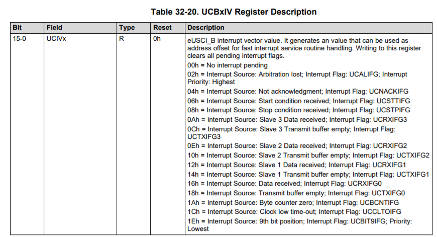
  • Thanks for the follow-up, Clemens. This is a good mid-point to help me get my code so that it handles the messages properly. I did notice that the flags in your ISR would cause incorrect operation. It would have been nice if the bitmask flags for UCBxIE and UCBxIFG lined up with the Interrupt Vector, but as you can see from the excerpts below (MSP430FR5x_6X User's Guide), the UCBxIV case statement is different. This explains why TI's example code always uses explicit hex numbers in their ISR, and puts the IFG name in the comments instead.

    Again, I appreciate you pointing me in the right direction! I add this hear for the sake of completeness for anyone else who finds this thread.

  • Allow me to quote msp430‍fr5969.h:

    /* USCI Interrupt Vector I2C Definitions */
    #define USCI_I2C_UCALIFG       (0x0002)       /* Interrupt Vector: I2C Mode: UCALIFG */
    #define USCI_I2C_UCNACKIFG     (0x0004)       /* Interrupt Vector: I2C Mode: UCNACKIFG */
    #define USCI_I2C_UCSTTIFG      (0x0006)       /* Interrupt Vector: I2C Mode: UCSTTIFG*/
    #define USCI_I2C_UCSTPIFG      (0x0008)       /* Interrupt Vector: I2C Mode: UCSTPIFG*/
    #define USCI_I2C_UCRXIFG3      (0x000A)       /* Interrupt Vector: I2C Mode: UCRXIFG3 */
    #define USCI_I2C_UCTXIFG3      (0x000C)       /* Interrupt Vector: I2C Mode: UCTXIFG3 */
    #define USCI_I2C_UCRXIFG2      (0x000E)       /* Interrupt Vector: I2C Mode: UCRXIFG2 */
    #define USCI_I2C_UCTXIFG2      (0x0010)       /* Interrupt Vector: I2C Mode: UCTXIFG2 */
    #define USCI_I2C_UCRXIFG1      (0x0012)       /* Interrupt Vector: I2C Mode: UCRXIFG1 */
    #define USCI_I2C_UCTXIFG1      (0x0014)       /* Interrupt Vector: I2C Mode: UCTXIFG1 */
    #define USCI_I2C_UCRXIFG0      (0x0016)       /* Interrupt Vector: I2C Mode: UCRXIFG0 */
    #define USCI_I2C_UCTXIFG0      (0x0018)       /* Interrupt Vector: I2C Mode: UCTXIFG0 */
    #define USCI_I2C_UCBCNTIFG     (0x001A)       /* Interrupt Vector: I2C Mode: UCBCNTIFG */
    #define USCI_I2C_UCCLTOIFG     (0x001C)       /* Interrupt Vector: I2C Mode: UCCLTOIFG */
    #define USCI_I2C_UCBIT9IFG     (0x001E)       /* Interrupt Vector: I2C Mode: UCBIT9IFG */
    
  • Ah hah! You are correct. I was looking at the set of defines in eusci_b_i2c.h, which redirects to msp430fr5969.h, but a different set of #define statements. I agree with you that your code does not have a bug. Still unfortunate that the bitmasks aren't the same, or that the naming convention isn't more clear about the difference. Thanks for pointing me to the correct #define statements.

  • Hi Paul,

    Were you able to successfully build an I2C slave message handler or do you still have any outstanding questions?

    Best regards,
    Caleb Overbay
  • Hi Caleb,

    I haven't finished the work at this point, but I've got a plan for the overall approach. I ended up buying O'Reilly's "Making Embedded Systems" as a guide for the right way to partition my code. I plan on writing the I2C driver to use the I2C interrupt handler to fill/read from the read and write ring buffers. Then use a different programming construct to read the messages and decide how to react. (Probably a loop in main() since I don't actually need super-low power operation).

    Thanks,

    Paul

  • Hi Paul,

    I'll be closing this thread for now but if you have any further questions during development please refer to Solutions to Common eUSCI and USCI Serial Communication Issues on MSP430 MCUs or reply on this thread and it will be re-opened. 

    Best regards, 
    Caleb Overbay

**Attention** This is a public forum