
- Ask a related questionWhat is a related question?A related question is a question created from another question. When the related question is created, it will be automatically linked to the original question.

Tool/software: Code Composer Studio
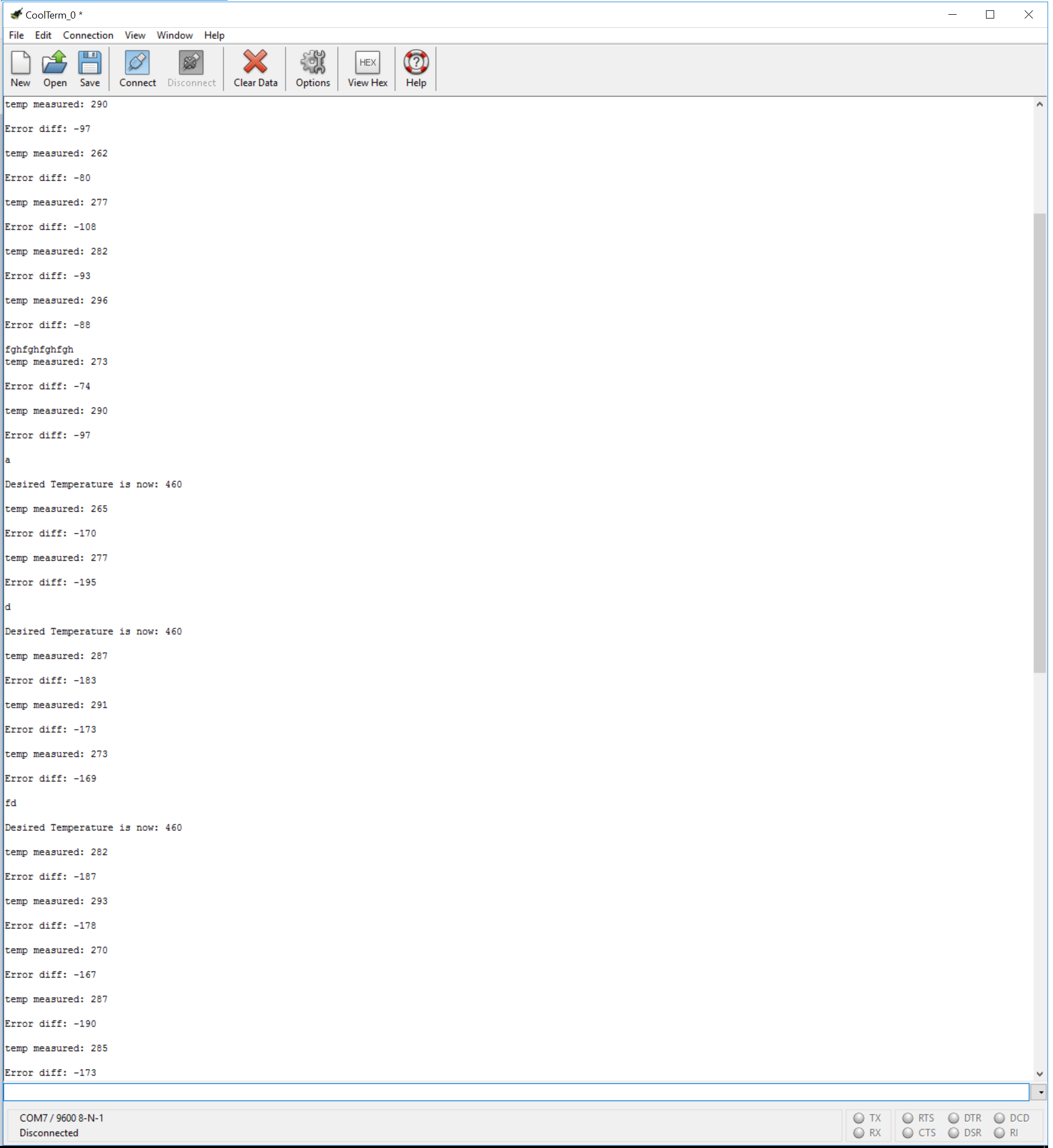
I posted a very similar question to this one a while ago, and I made several adjustments since then. The project I am working on involves a temperature sensor fan controller and the MSP430G2553. ADC values are measured from the sensor, and an error difference between a preset desired temperature and the current temperature are both printed over UART TX to the PC. The fan increases in speed via PWM, dependent on three if-statements that check the ADC10MEM value (i removed many other if-statements for cleaning). I used CoolTerm, by the way, to see the printed values.
The last thing I want to do is send multiple-character commands over UART RX, to set any desired temperature value. Right now, single character commands such as if(UCA0RXBUF == 'a') can set a SetDesiredTemp = 100. Also, I can type any random string of characters over UART RX, and the exact same string will be echoed over UART RX back to PC. This means I can confirm that my MSP430 is able to read a full string of characters and send it back to PC.
Here's where my issue arises. I know UART RX is doing what I want it to do, but using this code below, how can I check the string I sent to RX (or check the string echoed over TX) to see if a string command such as "Set Desired Temperature = " has been entered? And more importantly, how can I then convert the last three characters "100" into an integer that can be plugged into a SetDesiredTemp = 100 line?
I'll post my full code here for all to see. It compiles. I'm mainly hoping where in this code I can do the things described above, debugging for hours has gotten me nowhere.
#include <msp430g2553.h>
#include <stdio.h>
#include <string.h>
//Closed Loop: Temperature Sensor Fan Controller
/*** Initialize UART-Related Code ***/
volatile unsigned int current = 0; // store the currently read ADC10MEM at the beginning of the loop.
volatile unsigned int timer_count = 0;
static char data;
char buffer[32];
char buffer2[32];
void init_uart();
void init_timer();
void start_conversion();
void UARTSendArray(unsigned char *TxArray, unsigned char ArrayLength);
/*** Initialize Temperature Variables ***/
int error = 0; // subtract current from current to determine fan speed.
int SETtemperror = 370; //the default room temperature for making the error temperature values.
void (*uart_rx_isr_ptr)(unsigned char c);
void uart_set_rx_isr_ptr(void (*isr_ptr)(unsigned char c))
{
uart_rx_isr_ptr = isr_ptr;
}
void uart_putc(unsigned char c) // print to PC over TX one character at a time.
{
while (!(IFG2&UCA0TXIFG)); // USCI_A0 TX buffer ready?
UCA0TXBUF = c; // TX
}
void uart_puts(const char *str) // print any string message to PC with this function.
{
while(*str) uart_putc(*str++);
}
void uart_rx_isr(unsigned char c) { // UART RX Commands go here?
uart_putc(c);
P1OUT ^= BIT0; // toggle P1.0 (red led)
switch(c) {
case 'a': {
SETtemperror = 460;
uart_puts((char *)"\n\rDesired Temperature is now: 460\n\r");
}
}
}
void init_uart()
{
P1SEL = BIT1 + BIT2; // P1.1 = RXD, P1.2 = TXD
P1SEL2 = BIT1 + BIT2; // P1.1 = RXD, P1.2 = TXD
UCA0CTL1 |= UCSSEL_2; // SMCLK
UCA0BR0 = 104; // see baud rate divider above
UCA0BR1 = 0;
UCA0MCTL = UCBRS0; // modulation UCBRSx = 1
UCA0CTL1 &= ~UCSWRST; // ** initialize USCI state machine **
IE2 |= UCA0RXIE; // Enable USCI_A0 TX interrupt
}
void UARTSendArray(unsigned char *TxArray, unsigned char ArrayLength)
{
while(ArrayLength--) { // Loop until StringLength == 0 and post decrement
while(!(IFG2 & UCA0TXIFG)); // Wait for TX buffer to be ready for new data
UCA0TXBUF = *TxArray; //Write the character at the location specified py the pointer
TxArray++; //Increment the TxString pointer to point to the next character
}
}
void init_timer()
{
TA1CTL |= TACLR; // reset timer
TA1CTL = TASSEL_2 // SMCLK
+ ID_0 // input divider = 1
+ MC_2; // continuous mode, interrupt disabled
TA1CCTL0 = OUTMOD_2 // compare mode
+ CCIE // interrupt enabled
+ CCIFG;
/*** Timer0_A Set-Up ***/
DCOCTL = 0; // Select lowest DCO settings
BCSCTL1 = CALBC1_1MHZ; // Set DCO to 1 MHz
DCOCTL = CALDCO_1MHZ;
TA0CTL |= TASSEL_2 | MC_1 | ID_3;
TA0CCR0 |= 800;
TA0CCTL1 |= OUTMOD_7;
TA0CCR1 |= 0;
}
void start_conversion()
{
if ((ADC10CTL1 & ADC10BUSY) == 0) { // if not already converting
//P1OUT ^= 0x40; //green led
ADC10CTL0 |= ADC10SC;
ADC10SA = (unsigned) ¤t; // store latest ADC value into address
}
}
int main(void)
{
WDTCTL = WDTPW + WDTHOLD; // Stop WDT
init_uart();
init_timer();
/*** GPIO Set-Up ***/
P1DIR |= BIT6; // PWM output
P1SEL |= BIT6;
P2DIR |= BIT0 + BIT1 + BIT3 + BIT4;
/*** ADC10 Set-Up ***/
ADC10CTL0 = SREF_0 + ADC10SHT_3 + ADC10ON + ADC10IE + REFON + ENC; // ADC10ON, interrupt enabled. enable (but not yet start) conversions
ADC10DTC1 = 1; // one block per transfer
ADC10CTL1 = INCH_3 + SHS_0 + ADC10DIV_3 + ADC10SSEL_3 + CONSEQ_0; // clock source = SMCLK
//ADC10AE0 |= BIT0; // PA.1 ADC option select
// register ISR called when data was received
uart_set_rx_isr_ptr(uart_rx_isr);
// enable interrupts and put the CPU to sleep
_bis_SR_register(GIE+LPM0_bits);
unsigned char c = UCA0RXBUF;
uart_putc(c); // initialize retrieving of characters, initialize printing of characters.
uart_puts((char *)"\n\rTemperature Controller: ON and READY\n\r"); // signal that the main block has been initialized
unsigned int a = 0, delay = 50000, sec = 0;
for (;;)
{
current = ADC10MEM;
error = current - SETtemperror; // Calculate error difference from preset temperature. abs() removed.
//a = 0; sec = 0; // Delays to remove LED flickering
//while (a < delay) { a++; }
//while ((a >= delay) && (sec < 10)) { a = 0; sec++; }
if (error < 10) {
P2OUT &= ~BIT4; P2OUT &= ~BIT3; P2OUT &= ~BIT1; P2OUT &= ~BIT0; // 0000
TA0CCR1 = 0; // TA0CCR1 = ADC10MEM
}
if ((error >= 10) && (error < 100)) {
P2OUT &= ~BIT4; P2OUT |= BIT3; P2OUT |= BIT1; P2OUT &= ~BIT0; // 0000
TA0CCR1 = 400; // TA0CCR1 = ADC10MEM
}
if(error >= 100) {
P2OUT |= BIT4; P2OUT |= BIT3; P2OUT |= BIT1; P2OUT |= BIT0; // 1111
TA0CCR1 = 800; // TA0CCR1 = ADC10MEM
}
}
}
#pragma vector=ADC10_VECTOR // ADC10 interrupt service routine
__interrupt void ADC10_ISR(void)
{
__bic_SR_register_on_exit(CPUOFF); // Clear CPUOFF bit from 0(SR)
}
// INTERRUPT HANDLERS
#pragma vector = TIMER1_A0_VECTOR
__interrupt void Timer1_A0(void)
{
timer_count++;
if (timer_count > 16) { //default is 16 for 1 second refresh rate. set to 16 for slower data transfer
timer_count = 0;
start_conversion();
IE2 |= UCA0TXIE; // activate TX interrupt
IE2 |= UCA0RXIE; // Enable USCI_A0 RX interrupt
}
}
#pragma vector = USCIAB0TX_VECTOR
__interrupt void USCI0TX_ISR(void)
{
//P1DIR = 0x01;
//P1OUT ^= 0x01; //red led
unsigned int i = 0; // iterator pointers
sprintf(buffer, "temp measured: %d \n\r", (int)(current)); //output text to PC
//uart_puts((char *)"MSP430 harduart\n\r");
while (buffer[i] != '\0') {
while (!(IFG2 & UCA0TXIFG)); // USCI_A0 TX buffer ready?
UCA0TXBUF = buffer[i++];
}
unsigned int j = 0; // iterator pointers
sprintf(buffer2, "Error diff: %d \n\r", (int)(error)); //output text to PC
while (buffer2[j] != '\0') {
while (!(IFG2 & UCA0TXIFG)); // USCI_A0 TX buffer ready?
UCA0TXBUF = buffer2[j++];
}
IE2 &= ~UCA0TXIFG; // reset interrupt flag
}
#pragma vector=USCIAB0RX_VECTOR
__interrupt void USCI0RX_ISR(void)
{
if(uart_rx_isr_ptr != 0L) { // if there are more characters to send to RX buffer, keep sending characters.
(uart_rx_isr_ptr)(UCA0RXBUF);
}
switch(UCA0RXBUF) { // unsure where exactly the commands would go
case 'd': {
SETtemperror = 460;
uart_puts((char *)"\n\rDesired Temperature is now: 460\n\r");
}
}
}**Attention** This is a public forum


