This thread has been locked.

If you have a related question, please click the "Ask a related question" button in the top right corner. The newly created question will be automatically linked to this question.

CCS/MSP430G2553: MSP430G2553 TOUCH Clock affects counting

Part Number: MSP430G2553
Other Parts Discussed in Thread: MSP430FR2633

Tool/software: Code Composer Studio

Hello


I using MSP430G2553 and achieve touch detection by RO_PINOSC_TA0_WDTp Method , I encountered the following problems;
SMCLK is set to 1MHZ For a fixed capacitance change, the change in TA0CCR1 measurement is small and varies by approximately 5%.
SMCLK is set to the same capacitance change of 125KHZ. The TA0CCR1 measurement varies a lot, about 70%.
According to the measurement principle, the measurement window time becomes smaller, then TA0 counts base with smaller but does not affect the magnitude of change (this is my personal understanding do not know is correct).
This problem has been bothering me for a long time, please tell me why?


Thank you

Best regards

JackLiu

  • Hi,

    I'm having a little trouble understanding your question and I'm not familiar with the "RO_PINOSC_TA0_WDTp" method you've referenced. Can you please post a copy of your code so I can review it and see if you may be doing anything incorrectly that could explain this variation?

    Best regards,
    Caleb Overbay
  • Hi,

    Thanks Reply.
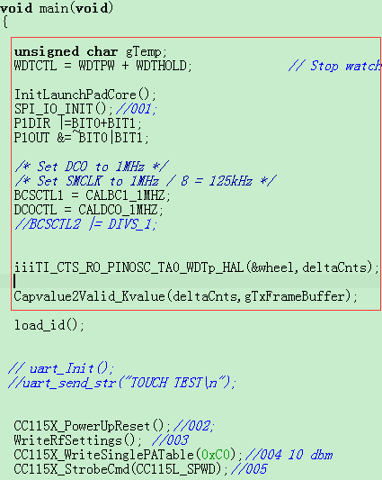
    Here is the pivotal code about RO_PINOSC_TA0_WDTp method.
    This code comes from the official demo,I have not changed.
    There is a picture, this is my main function.

    /////////////////////CODE///////////////////////////////////////////////////////////////////
    void iiiTI_CTS_RO_PINOSC_TA0_WDTp_HAL(const struct Sensor *group, unsigned int *counts) { uint8_t i; //** Context Save // Status Register: // WDTp: IE1, WDTCTL // TIMERA0: TA0CTL, TA0CCTL1 // Ports: PxSEL, PxSEL2 uint8_t contextSaveSR; uint8_t contextSaveIE1; uint16_t contextSaveWDTCTL; uint16_t contextSaveTA0CTL,contextSaveTA0CCTL1,contextSaveTA0CCR1; uint8_t contextSaveSel,contextSaveSel2; contextSaveSR = __get_SR_register(); contextSaveIE1 = IE1; contextSaveWDTCTL = WDTCTL; contextSaveWDTCTL &= 0x00FF; contextSaveWDTCTL |= WDTPW; contextSaveTA0CTL = TA0CTL; contextSaveTA0CCTL1 = TA0CCTL1; contextSaveTA0CCR1 = TA0CCR1; //** Setup Measurement timer*************************************************** // Choices are TA0,TA1,TB0,TB1,TD0,TD1 these choices are pushed up into the // capacitive touch layer. // Configure and Start Timer TA0CTL = TASSEL_3+MC_2; // TACLK, cont mode TA0CCTL1 = CM_3+CCIS_2+CAP; // Pos&Neg,GND,Cap IE1 |= WDTIE; // enable WDT interrupt for (i = 0; i<(group->numElements); i++) { // Context Save contextSaveSel = *((group->arrayPtr[i])->inputPxselRegister); contextSaveSel2 = *((group->arrayPtr[i])->inputPxsel2Register); // Configure Ports for relaxation oscillator *((group->arrayPtr[i])->inputPxselRegister) &= ~((group->arrayPtr[i])->inputBits); *((group->arrayPtr[i])->inputPxsel2Register) |= ((group->arrayPtr[i])->inputBits); //** Setup Gate Timer ******************************************************** // Set duration of sensor measurment WDTCTL = (WDTPW+WDTTMSEL+group->measGateSource+group->accumulationCycles); TA0CTL |= TACLR; // Clear Timer_A TAR if(group->measGateSource == GATE_WDT_ACLK) { __bis_SR_register(LPM3_bits+GIE); // Wait for WDT interrupt } else { __bis_SR_register(LPM0_bits+GIE); // Wait for WDT interrupt } TA0CCTL1 ^= CCIS0; // Create SW capture of CCR1 counts[i] = TA0CCR1; // Save result WDTCTL = WDTPW + WDTHOLD; // Stop watchdog timer // Context Restore *((group->arrayPtr[i])->inputPxselRegister) = contextSaveSel; *((group->arrayPtr[i])->inputPxsel2Register) = contextSaveSel2; } // End Sequence // Context Restore __bis_SR_register(contextSaveSR); if(!(contextSaveSR & GIE)) { __bic_SR_register(GIE); // } IE1 = contextSaveIE1; WDTCTL = contextSaveWDTCTL; TA0CTL = contextSaveTA0CTL; TA0CCTL1 = contextSaveTA0CCTL1; TA0CCR1 = contextSaveTA0CCR1; }

    ////////////////////////

    Best regards,
    JackLiu

  • Hi Jack,

    Thanks for providing this code. Again, I'm not familiar with the code you've posted but I'll look through it and see if I can decipher what is happening. Out of curiosity, can you point me to where you found this code?

    Additionally, I'd like to point out that if you're creating a new capacitive touch design, TI provides a line of MSP430 devices with our CapTIvate technology. This is much more advanced and has better support than the pin osc technology present in the MSP430G2553. 

    Best regards, 
    Caleb Overbay

  • Hi Caleb

    This section of the code comes from http://focus.ti.com/docs/toolsw/folders/print/capsenselibrary.html.

    I seem to have found the reason. measure  window longer, counter A overflow. Because it is a continuous

    technology mode, counting up to 0xFFFF again from 0X0000 start counting, which resulted in the wrong sensitivity calculation.

    Yes, I am also evaluating MSP430FR2633 now.CapTIvate chip performance is excellent, but the cost is higher compared to pin osc technology chip .


    Best regards,
    JackLiu

  • Hi Jack,

    Thanks for pointing me in the right direction and I'm glad you were able to solve the issue. Do you have anymore questions regarding this topic?

    Best regards,
    Caleb Overbay

**Attention** This is a public forum