This thread has been locked.

If you have a related question, please click the "Ask a related question" button in the top right corner. The newly created question will be automatically linked to this question.

MSP430F5132: MPPT TIDesign TIDR393

Part Number: MSP430F5132

Hi,

I saw there have 3 LEDs in TIDR393's(MPPT with MSP430F5132) schematic, i wnat to know what's the LED's status reflect to what satus of the system,

when i check the source code, I can't find out any related part of it, could you please tell me where is the source code of controlling the LED? Or what's the LED's behavior reflect to the systme's status? Thank you.

  • Hi Erik,
    I'll try to track down the designer.
    Do these LED's not correlate with the "LED's" in the GUI? Charging, Overload/Short, Battery Undervoltage?
  • Dear Sir,

    Thank you in advance, we really need the designer to tell us the behavior of these LEDs.

  • Hi Erik,
    Understood. I'll get a response from him soon.
  • Hi Erik,

    These are configurable LEDs that can be used for different indications important to a specific system. They were originally intended to be used as a bar graph display kind of the state of charge of the battery. We didn't implement this in the code in the end. So presently they do not perform any functions in the circuit; but can be configured to show indications like state of charge, current available from panel, fault conditions etc.

    Regards,

    Salil

  • hi,

    thanks for your reply, but i have some questions. The user guide mention about the state machine, but when i saw the source code, i can't find out any relationship of state machine between the source code and UG,

    In UG, it has standby status and LPM3/4 mode, but i cna't find it in source code.

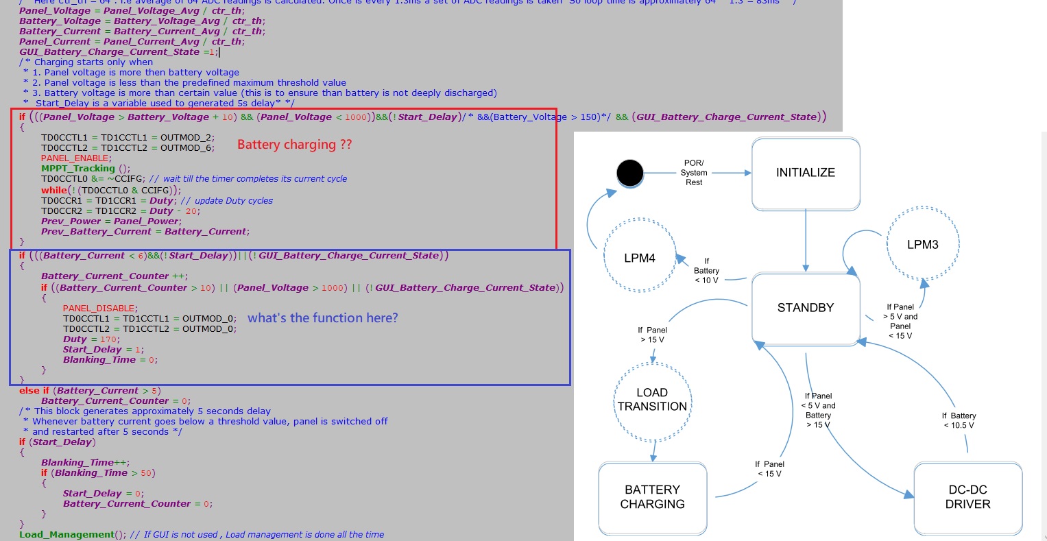
    picture below is the main code in super loop, inside of the red square seems be the function of Battery charging enable

    how about the blue square means? and what does it mean below the blue square(    else if (Battery_Current > 5)    Battery_Current_Counter = 0;)?

  • Erik,

    The state machine implemented is more of a pseudo-state machine. It's controlled via interrupts that set flags for the main loop. The central standby is the main loop idling, waiting for data from an ISR. When the ADC and DMA transfers are complete, a flag will alert the main loop to enter the battery charge and DC-DC Driver routines. The LPM3 and 4 functionality are not present in the code that is available with the design today but would be straightforward enough to add.

    You are correct that the block you have highlighted in red controls the battery charging system. The MPPT_Tracking function determines current flow and duty cycle, then it's set to the PWM outputs.

    The blue block disables the panel if the average current from the battery drops too low or starts to reverse for a set amount of time. This is done by incrementing the Battery_Current_Counter. If the battery current restores itself during this period, the shutdown is halted and the panel remains on. This is what the "else if" section of code does.

    This is to prevent reverse current from potentially damaging the panel when there is insufficient solar irradiation. When the panel voltage rises above the battery voltage again, it will enable the panel to continue charging.

    Please let me know if you need any additional clarification on this topic.

  • Dear Bart,

    Thanks for your reply, I neary crystal clear what's the behavior of this FW by your explanation.

    Last thing, so if the judgement of the red text below is true, that means the battery is nearly charging full, so turn off the Solar Panel, am i right?

        if (((Battery_Current < 6)&&(!Start_Delay))||(!GUI_Battery_Charge_Current_State))
        {
         Battery_Current_Counter ++;
         if ((Battery_Current_Counter > 10) || (Panel_Voltage > 1000) || (!GUI_Battery_Charge_Current_State))
         {
          PANEL_DISABLE;
          TD0CCTL1 = TD1CCTL1 = OUTMOD_0;
          TD0CCTL2 = TD1CCTL2 = OUTMOD_0;
          Duty = 170;
          Start_Delay = 1;
          Blanking_Time = 0;
         }
        }

**Attention** This is a public forum