This thread has been locked.

If you have a related question, please click the "Ask a related question" button in the top right corner. The newly created question will be automatically linked to this question.

RTOS/MSP430FR6972: the question of RTC wake LPM3.5

Part Number: MSP430FR6972

Tool/software: TI-RTOS

Good day,

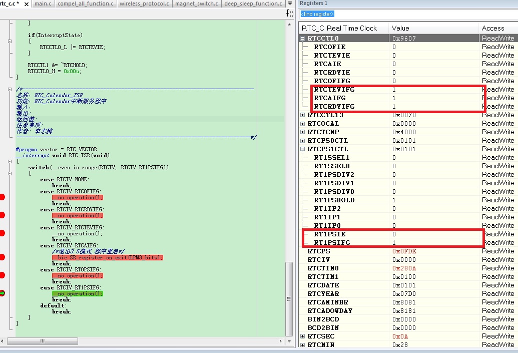
I have a trouble to use RTCAIE interrupt wake  LPM3.5 . Before Entering LPM3.5, I set a 1min alarm of RTC and the value of RTCCTL0L is 0x20.   When the 1min alarm arrived and RTC waked the cpu, I find the RTCCTL0L = 0x07. Then the program always enters the ISR of RTC , but it didn't execute any case . The program run  abnormality.the ISR program as following:

#pragma vector = RTC_VECTOR
__interrupt void RTC_ISR(void)
{
    switch(__even_in_range(RTCIV, RTCIV_RT1PSIFG))
    {
        case RTCIV_NONE:      
            break;       
        case RTCIV_RTCOFIFG: 
            break;        
        case RTCIV_RTCRDYIFG:
            break;              
        case RTCIV_RTCTEVIFG:
            _EINT();
            RtcCount++;
            if(RtcCount == 1)              
            {
                RtcCount = 0; 
                g_WakeRegister |= WAKE_RTC_TIME_ARRIVE;
                __bic_SR_register_on_exit(LPM3_bits);
               
            }
            break;              
        case RTCIV_RTCAIFG: 
            /*退出3.5模式,程序重启*/
            __bic_SR_register_on_exit(LPM3_bits);
            break;        
        case RTCIV_RT0PSIFG:  
            break;       
        case RTCIV_RT1PSIFG:  
            break;        
        default: 
            break;
    }
}

I hope you can help me  .

Best Regards

Jent

  • Hi Jent,

    You can set a breakpoint in the RTC ISR and see the value of RTCIV when program enters the ISR. Besides, you can run official code example an see if any abnormal. If the code example is correct, you can compare your code with example code to find the difference.

    Best Regards,
    Winter Yu
  • Thank you Winter,

    I make a simple test ,the code as following:

    void main( void )
    {
        // close watch dog
    	WDTCTL = WDTPW | WDTHOLD; 
    	
    	// config fram for 16MHz MCLK
    	FRCTL0 = FRCTLPW | NWAITS_1;
    	GCCTL0 &= ~UBDIE;
    	GCCTL0 |= FRPWR|FRLPMPWR;
    	FRCTL0_H = 0x00u;
    	
    	// config clock
        PJSEL0 = BIT4 | BIT5;                           
        CSCTL0_H = CSKEY_H;  
        CSCTL1 = DCORSEL | DCOFSEL_4;                        
        CSCTL2 = SELA__LFXTCLK|SELM__DCOCLK|SELS__DCOCLK;   //MCLK 16MHz SMCLK 16MHz ACLK 32.768KHz
        CSCTL3 = DIVA__1|DIVS__1|DIVM__1;
        CSCTL4 &= ~LFXTOFF;      
        do
        {
            CSCTL5 &= ~LFXTOFFG;                
            SFRIFG1 &= ~OFIFG;
        } while (SFRIFG1 & OFIFG);  
        CSCTL4 &= (~(LFXTDRIVE0 | LFXTDRIVE1));  
        CSCTL0_H = 0;   
        
        __bis_SR_register(GIE);
    	PM5CTL0 &= ~LOCKLPM5;
    	
    	//int rtc
    	RTCCTL0_H = RTCKEY_H;
        RTCCTL0_L = 0x00u;
        RTCCTL1 = 0x00u;
        RTCCTL1 |= RTCHOLD|RTCMODE;
        RTCCTL3 = 0X00u;
        RTCPS0CTL = RT0PSHOLD;
        RTCPS1CTL = RT1PSHOLD;
        RTCCTL0_H = 0x00u;
    	
    	//write rtc int time
    	RTCCTL0_H = RTCKEY_H;
        RTCCTL1 |= RTCHOLD| RTCMODE; 
        RTCSEC = 0;
        RTCMIN = 0;
        RTCHOUR = 1;
        RTCDOW = 1;
        RTCDAY = 1;
        RTCMON = 1;
        RTCYEAR = 2000;
        RTCCTL1 &= ~RTCHOLD;
        RTCCTL0_H = 0x00u;
    	
    	//set rtc alarm
    	RTCCTL0_H = RTCKEY_H;
        RTCCTL1 |= RTCHOLD| RTCMODE; 
        RTCCTL0_L = 0x00u;
        RTCAMIN = 0x00u;
        RTCAHOUR = 0x00u;
        RTCADOW = 0x00u;
        RTCADAY = 0x00u;
        RTCAMIN = RTCAE |1;
        RTCAHOUR = RTCAE |1;
        RTCADOW = RTCAE |1;
        RTCADAY = RTCAE |1;
        RTCCTL0_L |= RTCAIE;
        RTCCTL1 &= ~RTCHOLD;
        RTCCTL0_H = 0x00u;
    	
    	//enter lpm3.5
    	PMMCTL0_H = PMMPW_H;
    	PMMCTL0_L &= ~(SVSHE);
    	PMMCTL0_L |= PMMREGOFF;                 
        PMMCTL0_H = 0; 
        __bis_SR_register(LPM3_bits | GIE);
    }


    #pragma vector = RTC_VECTOR
    __interrupt void RTC_ISR(void)
    {
        switch(__even_in_range(RTCIV, RTCIV_RT1PSIFG))
        {
            case RTCIV_NONE:      
                break;       
            case RTCIV_RTCOFIFG: 
                __no_operation();
                break;        
            case RTCIV_RTCRDYIFG:
                __no_operation();
                break;              
            case RTCIV_RTCTEVIFG:
                __no_operation();
                break;              
            case RTCIV_RTCAIFG: 
                __bic_SR_register_on_exit(LPM3_bits);
                break;        
            case RTCIV_RT0PSIFG:  
                __no_operation();
                break;       
            case RTCIV_RT1PSIFG:  
                __no_operation();
                break;        
            default: 
                break;
        }
    }

    I found when the cpu wake from LPM3.5  and  execute "__bis_SR_register(GIE);", the cpu will always enter RTC ISR. In the RTC ISR, cpu  execute "case RTCIV_RT1PSIFG " all the time .

  • the register value as following :

    when the cpu wake up, why is the RTCTEVIFG ,RT1SIFG will be set ?

    Best regards

    Jent

  • Hi Jent,

    For using LPM3.5 mode, you can refer to this official code example.

    /* --COPYRIGHT--,BSD_EX
     * Copyright (c) 2014, Texas Instruments Incorporated
     * All rights reserved.
     *
     * Redistribution and use in source and binary forms, with or without
     * modification, are permitted provided that the following conditions
     * are met:
     *
     * *  Redistributions of source code must retain the above copyright
     *    notice, this list of conditions and the following disclaimer.
     *
     * *  Redistributions in binary form must reproduce the above copyright
     *    notice, this list of conditions and the following disclaimer in the
     *    documentation and/or other materials provided with the distribution.
     *
     * *  Neither the name of Texas Instruments Incorporated nor the names of
     *    its contributors may be used to endorse or promote products derived
     *    from this software without specific prior written permission.
     *
     * THIS SOFTWARE IS PROVIDED BY THE COPYRIGHT HOLDERS AND CONTRIBUTORS "AS IS"
     * AND ANY EXPRESS OR IMPLIED WARRANTIES, INCLUDING, BUT NOT LIMITED TO,
     * THE IMPLIED WARRANTIES OF MERCHANTABILITY AND FITNESS FOR A PARTICULAR
     * PURPOSE ARE DISCLAIMED. IN NO EVENT SHALL THE COPYRIGHT OWNER OR
     * CONTRIBUTORS BE LIABLE FOR ANY DIRECT, INDIRECT, INCIDENTAL, SPECIAL,
     * EXEMPLARY, OR CONSEQUENTIAL DAMAGES (INCLUDING, BUT NOT LIMITED TO,
     * PROCUREMENT OF SUBSTITUTE GOODS OR SERVICES; LOSS OF USE, DATA, OR PROFITS;
     * OR BUSINESS INTERRUPTION) HOWEVER CAUSED AND ON ANY THEORY OF LIABILITY,
     * WHETHER IN CONTRACT, STRICT LIABILITY, OR TORT (INCLUDING NEGLIGENCE OR
     * OTHERWISE) ARISING IN ANY WAY OUT OF THE USE OF THIS SOFTWARE,
     * EVEN IF ADVISED OF THE POSSIBILITY OF SUCH DAMAGE.
     *
     *******************************************************************************
     * 
     *                       MSP430 CODE EXAMPLE DISCLAIMER
     *
     * MSP430 code examples are self-contained low-level programs that typically
     * demonstrate a single peripheral function or device feature in a highly
     * concise manner. For this the code may rely on the device's power-on default
     * register values and settings such as the clock configuration and care must
     * be taken when combining code from several examples to avoid potential side
     * effects. Also see www.ti.com/grace for a GUI- and www.ti.com/msp430ware
     * for an API functional library-approach to peripheral configuration.
     *
     * --/COPYRIGHT--*/
    //******************************************************************************
    //   MSP430FR69xx Demo - RTC_C, LPM3.5, & alarm
    //
    //   Description: The RTC_C module is used to set the time, start RTC operation,
    //   and read the time from the respective RTC registers. Software will set the
    //   original time to 11:59:30 am on Friday October 7, 2011. Then the RTC will
    //   be activated through software, and an alarm will be created for the next
    //   minute (12:00:00 pm). The device will then enter LPM3.5 awaiting
    //   the event interrupt. Upon being woken up by the event, the LED on the board
    //   will be set.
    //
    //   ACLK = 32.768kHz, MCLK = SMCLK = DCO = ~1MHz
    //
    //               MSP430FR6989
    //             -----------------
    //         /|\|              XIN|-
    //          | |                 | 32kHz
    //          --|RST          XOUT|-
    //            |                 |
    //            |             P1.0|--> LED
    //
    //   William Goh
    //   Texas Instruments Inc.
    //   April 2014
    //   Built with IAR Embedded Workbench V5.60 & Code Composer Studio V6.0
    //******************************************************************************
    #include <msp430.h>
    
    void Board_Init(void);
    void RTC_Init(void);
    void EnterLPM35(void);
    void WakeUpLPM35(void);
    
    volatile unsigned i;
    
    int main(void)
    {
      WDTCTL = WDTPW | WDTHOLD;                 // Stop WDT
    
      // Determine whether we are coming out of an LPMx.5 or a regular RESET.
      if (SYSRSTIV == SYSRSTIV_LPM5WU)
      {
        // When woken up from LPM3.5, reinit
        WakeUpLPM35();                          // LPMx.5 wakeup specific init code
        __enable_interrupt();                   // The RTC interrupt should trigger now...
        while (1);                              // Forever loop after returning from RTC ISR.
      }
      else
      {
        // Init board & RTC, then enter LPM3.5
        Board_Init();                           // Regular init code for GPIO and CS
        RTC_Init();                             // Regular init code for RTC_B
        EnterLPM35();                           // This function will NOT return.
      }
    }
    
    void Board_Init(void)
    {
      // Port Configuration
      P1OUT = 0;
      P1DIR = 0xFF;
    
      P2OUT = 0;
      P2DIR = 0xFF;
    
      P3OUT = 0;
      P3DIR = 0xFF;
    
      P4OUT = 0;
      P4DIR = 0xFF;
    
      P5OUT = 0;
      P5DIR = 0xFF;
    
      P6OUT = 0;
      P6DIR = 0xFF;
    
      P7OUT = 0;
      P7DIR = 0xFF;
    
      P8OUT = 0;
      P8DIR = 0xFF;
    
      P9OUT = 0;
      P9DIR = 0xFF;
    
      P10OUT = 0;
      P10DIR = 0xFF;
    
      PJOUT = 0x00;
      PJSEL0 |= BIT4 | BIT5;
      PJDIR = 0xFFFF;
    
      // Disable the GPIO power-on default high-impedance mode to activate
      // previously configured port settings
      PM5CTL0 &= ~LOCKLPM5;
    
      // Setup Clocks
      CSCTL0_H = CSKEY >> 8;                    // Unlock CS registers
      CSCTL1 = DCOFSEL_0;                       // Set DCO to 1MHz
      CSCTL2 = SELA__LFXTCLK | SELS__DCOCLK | SELM__DCOCLK; // set ACLK = XT1; MCLK = DCO
      CSCTL3 = DIVA__1 | DIVS__1 | DIVM__1;     // Set all dividers to 1
      CSCTL4 &= ~LFXTOFF;                       // Enable LFXT1
      do
      {
        CSCTL5 &= ~LFXTOFFG;                    // Clear XT1 fault flag
        SFRIFG1 &= ~OFIFG;
      } while (SFRIFG1 & OFIFG);                // Test oscillator fault flag
      CSCTL0_H = 0;                             // Lock CS registers
    }
    
    void RTC_Init(void)
    {
      // Configure RTC_C
      RTCCTL0_H = RTCKEY_H;                     // Unlock RTC key protected registers
      RTCCTL0_L = RTCTEVIE;                     // enable RTC event interrupt for each minute
      RTCCTL1 = RTCBCD | RTCHOLD | RTCMODE | RTCTEV__MIN; // BCD mode, RTC hold, in RTC mode
      RTCYEAR = 0x2011;                         // Year = 0x2011
      RTCMON = 0x10;                            // Month = 0x10 = October
      RTCDAY = 0x07;                            // Day = 0x07 = 7th
      RTCDOW = 0x05;                            // Day of week = 0x05 = Friday
      RTCHOUR = 0x11;                           // Hour = 0x11
      RTCMIN = 0x59;                            // Minute = 0x59
      RTCSEC = 0x30;                            // Seconds = 0x30
    
      RTCCTL1 &= ~RTCHOLD;                      // Start RTC calendar mode
      RTCCTL0_H = 0;                            // Lock RTC key protected registers
    }
    
    void EnterLPM35(void)
    {
      PMMCTL0_H = PMMPW_H;                      // Open PMM Registers for write
      PMMCTL0_L |= PMMREGOFF;                   // and set PMMREGOFF
    
      // Enter LPM3.5 mode with interrupts enabled. Note that this operation does
      // not return. The LPM3.5 will exit through a RESET event, resulting in a
      // re-start of the code.
      __bis_SR_register(LPM4_bits | GIE);
    }
    
    void WakeUpLPM35(void)
    {
      // Restore Port settings
      P1OUT = 0x00;
      P1DIR = 0xFF;
      P2OUT = 0x00;
      P2DIR = 0xFF;
      P3OUT = 0x00;
      P3DIR = 0xFF;
      P4OUT = 0x00;
      P4DIR = 0xFF;
      PJOUT = 0x00;
      PJSEL0 |= BIT4 | BIT5;
      PJDIR = 0xFFFF;
    
      // Reconfig/start RTC
      RTCCTL0_H = RTCKEY_H;                     // Unlock RTC key protected registers
      RTCCTL0_L |= RTCTEVIE;                    // enable RTC event interrupt for each minute
      RTCCTL1 = RTCBCD | RTCHOLD | RTCTEV__MIN; // BCD mode, RTC hold
      RTCCTL1 &= ~RTCHOLD;
      RTCCTL0_H = 0;                            // Lock RTC key protected registers
    
      // Disable the GPIO power-on default high-impedance mode to activate
      // previously configured port settings. This will also re-activate the RTC
      // settings.
      PM5CTL0 &= ~LOCKLPM5;
    
      // Restore Clocks so that RTC will be read
      CSCTL0_H = CSKEY >> 8;                    // Unlock CS registers
      CSCTL1 = DCOFSEL_0;                       // Set DCO to 1MHz
      CSCTL2 = SELA__LFXTCLK | SELS__DCOCLK | SELM__DCOCLK; // Set ACLK = XT1; MCLK = DCO
      CSCTL3 = DIVA__1 | DIVS__1 | DIVM__1;     // Set all dividers to 1
      CSCTL4 &= ~LFXTOFF;                       // Enable LFXT1
      do
      {
        CSCTL5 &= ~LFXTOFFG;                    // Clear XT1 fault flag
        SFRIFG1 &= ~OFIFG;
      }while (SFRIFG1&OFIFG);                   // Test oscillator fault flag
      CSCTL0_H = 0;                             // Lock CS registers
    }
    
    #if defined(__TI_COMPILER_VERSION__) || defined(__IAR_SYSTEMS_ICC__)
    #pragma vector=RTC_VECTOR
    __interrupt void RTC_ISR(void)
    #elif defined(__GNUC__)
    void __attribute__ ((interrupt(RTC_VECTOR))) RTC_ISR (void)
    #else
    #error Compiler not supported!
    #endif
    {
      switch (__even_in_range(RTCIV, RTCIV_RTCOFIFG)){
        case RTCIV_NONE: break;
        case RTCIV_RTCRDYIFG: break;
        case RTCIV_RTCTEVIFG:
          P1OUT |= BIT0;                        // Turn on LED
          break;
        case RTCIV_RTCAIFG: break;
        case RTCIV_RT0PSIFG: break;
        case RTCIV_RT1PSIFG: break;
        case RTCIV_RTCOFIFG: break;
      }
    }

    Best Regards,

    Winter Yu

  • Hi Jent,

    Besides, I think the  MSP430FR58xx, MSP430FR59xx, and MSP430FR6xx Family User's Guide (Rev. O) may help you. The section 1.4.3.1 Enter LPMx.5 and 1.4.3.2 Exit and Wake up From LPM3.5 describe the detail operation for using LPM3.5.

    Best Regards,

    Winter Yu

  • Thank you Winter,
    I found the reason is PM5CTL0 &= ~LOCKLPM5;. If I set PM5CTL0 &= ~LOCKLPM5 before init System clock , I program is ok.

    Best regards
    Jent

**Attention** This is a public forum