Other Parts Discussed in Thread: SN74AUP1G34
I posted about this almost a year ago:
https://e2e.ti.com/support/microcontrollers/msp430/f/166/t/585032
but wanted to revisit it to see if my solution is ok.
To briefly recap, I want to embed a CP2102 USB-to Serial adapter in an MSP430G2553 circuit so firmware updates can be performed with only a USB cable and the right software. I won't be using the special signalling pattern on Test and /Reset to enter BSL, but need to use DTR to reset the processor from the PC software. The problem is that the CP2102 sinks current at all its I/O pins when it is powered down, and it would always be powered down unless it is powered up from a connected USB cable. So if I connect DTR to the processor's /Reset pin, that pin would be clamped low, which is no good. I asked earlier about using a capacitor in series, but was concerned about what would happen when DTR goes back high - in theory there would be a 6.6V spike at the /Reset pin.
I've ended up with this circuit:
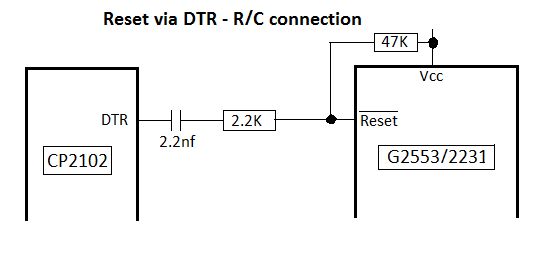
The capacitor is the standard 2.2nF value that is supposed to still allow SBW JTAG flashing, except that it's connected to DTR, which is effectvely at ground when the CP2102 is powered down. The 2.2K resistor is there to limit protection diode current to less than 2 mA, as specified in the datasheet, when DTR goes high.
This appears to work ok. The negative-going reset pulse when DTR goes low goes almost to ground, and stays under 2V for almost 100 uSec.
I just wanted to be sure I haven't overlooked anything. If anyone sees a problem, please post.
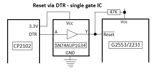
By the way, the solution suggested in the original thread of using a single gate non-inverting buffer would also work. The SN74AUP1G34 seems to be the best choice for that.