This thread has been locked.

If you have a related question, please click the "Ask a related question" button in the top right corner. The newly created question will be automatically linked to this question.

MSP430FR2633: MSP430FR2633

Part Number: MSP430FR2633
Other Parts Discussed in Thread: CAPTIVATE-FR2633

Hello Support,

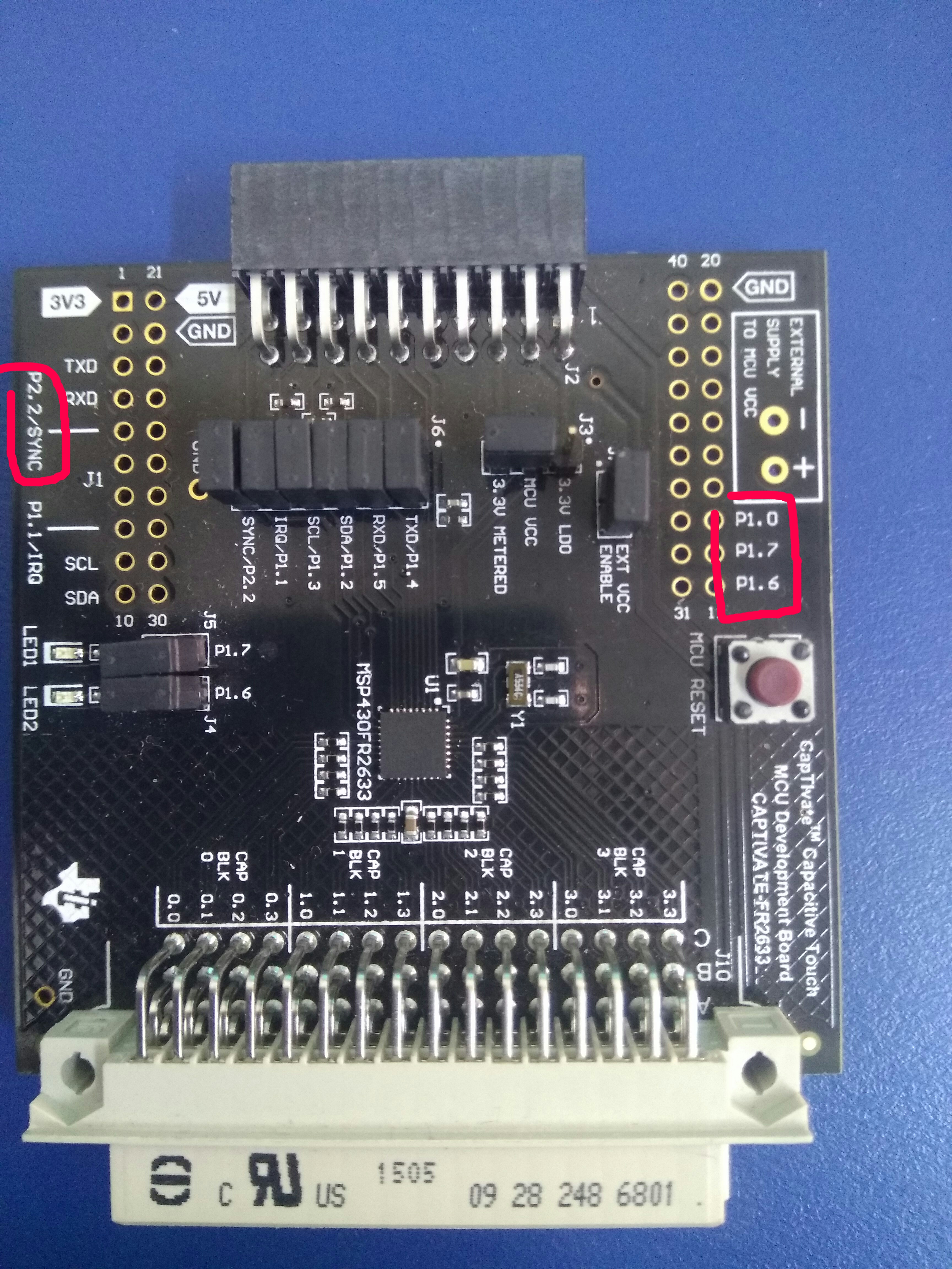
I am Working on a Project and I am using MSP430FR2633, I need to use the GPIO pins,but cannot find them on the board as they are not labelled

I have read the Datasheet and I know there are 19 GPIO ports but only four are labelled (P1_6, P1_7, P1_0,P2_2).

How can I identify the other GPIO pins?

  • Hello Yadnyesh,

    Thank you for your post. What board are you referring to? Is it an EVM? If so, the accessibility to those GPIOs could be limited by the specific design.

    In Table 4-2 in the datasheet, there are quite a few GPIOs listed (snippet shown below). Now, some aren't available in certain packages, so watch out for that.

    Hope this helps!

    Regards,

    James

    MSP Customer Applications

  • Hi James,

    Thank you for your quick response,

    I am using an EVM. I am working on a project and I am currently using BSWP touch panel, I am trying to control Home appliances using the touch panel and Relays(If you can suggest something better please do). Currently I can control Four appliances using the pins (P1_0,P1_7,P1_6,P2_2) which are labelled on the MSP430FR2633 launchpad.I need more GPIO pins to control more appliances but I cannot find them on the launchpad.

    I tried to check the connectivity of the pins on the IC to the plug-ins labelled 

    For eg:- For P1_0 I connected the Positive terminal of Multimeter to pin 7 of the IC and the negative to plug-in(13) (marked by red circle in the second picture).I got the connectivity for P1_0, P1_7,P1_6,P2_2.

    For the plug-ins which are not labelled I tried the same, I connected the positive terminal to the IC pin and Negative terminal to the remaining plug-ins trying to find the connection between but could not.

    http://www.ti.com/tool/msp-capt-fr2633?keyMatch=msp430fr2633%20development%20kit&tisearch=Search-EN-Everything#descriptionArea

  • Hello Yadnyesh,

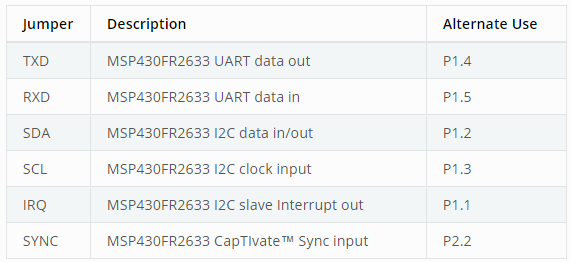
    Sounds like an interesting application! Take a look at the J6 headers. These pins could be used as GPIOs although it may affect the communication with the GUI. If I remember correctly, the GUI either uses UART or I2C, so if UART is used, you could utilize the I2C pins and remove the pull-up resistors, R1, R2, and R22. I would recommend looking at the CAPTIVATE-FR2633 schematic (found under the "Download Design Files" link on the MSP-CAPT-FR2633 product folder).

    Regards,

    James

    MSP Customer Applications

**Attention** This is a public forum