This thread has been locked.

If you have a related question, please click the "Ask a related question" button in the top right corner. The newly created question will be automatically linked to this question.

MSP430FW425: Regarding LC sense

Part Number: MSP430FW425

Hi,

I am using the sample code provided for LC sense for sensing using single inductor.
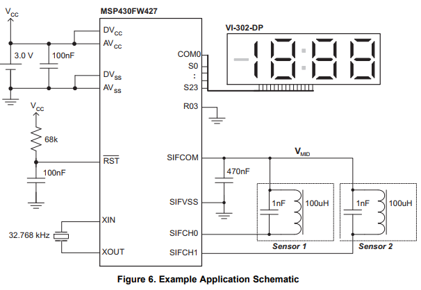
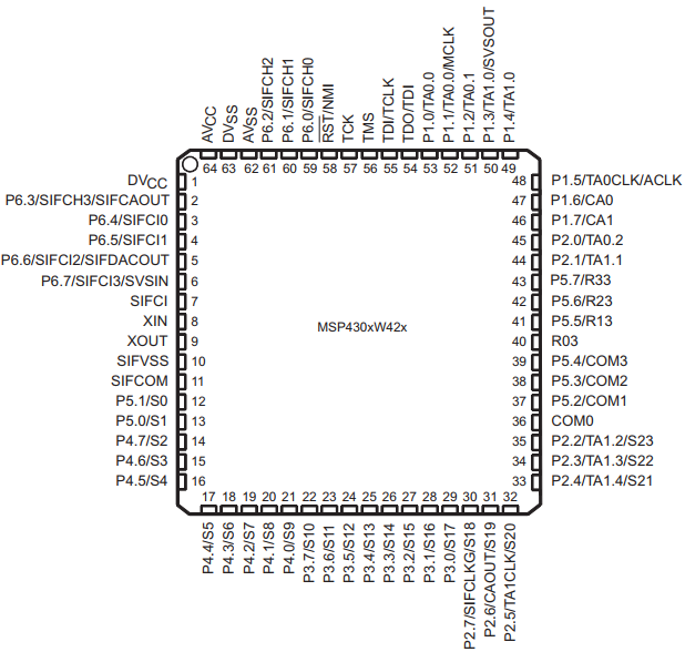
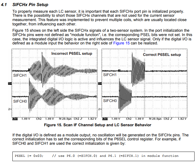
I am using SIFCH0(P6.0) pin for Inductor and SIFCOM as DAC output which is given as sample schematic . i believe my hardware is perfect but yet i dont get any interrupt for sensing at inductor with metal. Is there any change required in the code provided, plzz help as soon as possible.
Thanks regards

  • Hello Hari,

    Have you had a chance to read through the Rotation Detection With the MSP430™ Scan Interface app note? It has a lot of valuable information. Also, which source code are you using? Where did you find it?

    In Section 3.1.1, it mentions that during the initialization of the Scan Interface module it is necessary to configure the required pins for module functionality (for example, P6SEL=0x01). Otherwise the digital input influences the measurement. In addition, the damping of other Scan IF inputs when multiple LC sensors are used will not function correctly if the module function is not selected. For additional information, see Section 4.1.

    Regards,

    James

    MSP Customer Applications

  • Hello James,
    I have referred the application note SLAA222B, which had a link of the source code, which has one sensor and two sensor code. I am using one sensor code and commented the lcd code (changed P6SEL=0x03 to P6SEL=0x01). If required i would send you the schematic design.
    Thanks regards.

  • Hello Hari,

    Have you compared your schematic to the example schematic shown in Figure 6 in SLAA222B? Next, I would refer to the Pin Designation figure in the datasheet to make sure that both your pin connections (your board versus the board used with source code) and pin configurations (e.g. PxOUT, PxDIR, PxSEL, etc.) are correct. Changing P6SEL from 0x03 to 0x01 makes sense if you're just using SIFCH0.


    Only the LC sensor(s), a bypass capacitor (between SIFCOM and SIFVSS) for the VMID voltage generation and a 32.768 kHz reference clock (crystal) needs to be connected to the MSP430™ MCU to establish proper Scan IF module operation. Please confirm that these exist and are working correctly before digging deeper into the issue.

    Regards,

    James

    MSP Customer Applications

  • Dear James,

    I have checked the bypass capacitor and pins are also same. using oscilloscope i have checked the oscillations too. When i am getting metal near to the inductor the oscillation is getting compressed but i am not getting the interrupt.

    i am attaching the schematic for your reference but using only single sensor i.e., SIFCH0

    Thanks regards.

    A. Hari Adinarayana.

  • Hello Hari,

    Thank you for sharing your schematic. I didn't see anything wrong after looking at it.

    Which interrupt are you referring to? Are you trying to set a breakpoint in the ISR_ScanIF() ISR in the single sensor code example?

    /*---------------------------------------------------------------------------*/
    
    #pragma vector=SCANIF_VECTOR
      __interrupt void ISR_ScanIF(void)
    {
      SIFCTL1 &= ~0x0020;   // reset interrupt flag
      DisplayWord(SIFCNT);  // display the SIFCNT value
    }

    In the ISR above, can you try adding a NOP after the DisplayWord() function and put a breakpoint there?

    __no_operation();

    If you can't reach this breakpoint, can you confirm that the code gets to the while() loop in main()?

    // THIS PROGRAM IS PROVIDED "AS IS". TI MAKES NO WARRANTIES OR
    // REPRESENTATIONS, EITHER EXPRESS, IMPLIED OR STATUTORY, 
    // INCLUDING ANY IMPLIED WARRANTIES OF MERCHANTABILITY, FITNESS 
    // FOR A PARTICULAR PURPOSE, LACK OF VIRUSES, ACCURACY OR 
    // COMPLETENESS OF RESPONSES, RESULTS AND LACK OF NEGLIGENCE. 
    // TI DISCLAIMS ANY WARRANTY OF TITLE, QUIET ENJOYMENT, QUIET 
    // POSSESSION, AND NON-INFRINGEMENT OF ANY THIRD PARTY 
    // INTELLECTUAL PROPERTY RIGHTS WITH REGARD TO THE PROGRAM OR 
    // YOUR USE OF THE PROGRAM.
    //
    // IN NO EVENT SHALL TI BE LIABLE FOR ANY SPECIAL, INCIDENTAL, 
    // CONSEQUENTIAL OR INDIRECT DAMAGES, HOWEVER CAUSED, ON ANY 
    // THEORY OF LIABILITY AND WHETHER OR NOT TI HAS BEEN ADVISED 
    // OF THE POSSIBILITY OF SUCH DAMAGES, ARISING IN ANY WAY OUT 
    // OF THIS AGREEMENT, THE PROGRAM, OR YOUR USE OF THE PROGRAM. 
    // EXCLUDED DAMAGES INCLUDE, BUT ARE NOT LIMITED TO, COST OF 
    // REMOVAL OR REINSTALLATION, COMPUTER TIME, LABOR COSTS, LOSS 
    // OF GOODWILL, LOSS OF PROFITS, LOSS OF SAVINGS, OR LOSS OF 
    // USE OR INTERRUPTION OF BUSINESS. IN NO EVENT WILL TI'S 
    // AGGREGATE LIABILITY UNDER THIS AGREEMENT OR ARISING OUT OF 
    // YOUR USE OF THE PROGRAM EXCEED FIVE HUNDRED DOLLARS 
    // (U.S.$500).
    //
    // Unless otherwise stated, the Program written and copyrighted 
    // by Texas Instruments is distributed as "freeware".  You may, 
    // only under TI's copyright in the Program, use and modify the 
    // Program without any charge or restriction.  You may 
    // distribute to third parties, provided that you transfer a 
    // copy of this license to the third party and the third party 
    // agrees to these terms by its first use of the Program. You 
    // must reproduce the copyright notice and any other legend of 
    // ownership on each copy or partial copy, of the Program.
    //
    // You acknowledge and agree that the Program contains 
    // copyrighted material, trade secrets and other TI proprietary 
    // information and is protected by copyright laws, 
    // international copyright treaties, and trade secret laws, as 
    // well as other intellectual property laws.  To protect TI's 
    // rights in the Program, you agree not to decompile, reverse 
    // engineer, disassemble or otherwise translate any object code 
    // versions of the Program to a human-readable form.  You agree 
    // that in no event will you alter, remove or destroy any 
    // copyright notice included in the Program.  TI reserves all 
    // rights not specifically granted under this license. Except 
    // as specifically provided herein, nothing in this agreement 
    // shall be construed as conferring by implication, estoppel, 
    // or otherwise, upon you, any license or other right under any 
    // TI patents, copyrights or trade secrets.
    //
    // You may not use the Program in non-TI devices.
    //
    /*****************************************************************************/
    /*  MSP430FW427                                                              */
    /*  Simple 1 Sensor Demo. A LED on P1.7 will show if the coil is above metal */
    /*  (LED is off) or if the coild is not above metal (LED is on). On the LCD  */ 
    /*  display the SIFCNT value is shown.                                       */
    /*                                     Texas Instruments Deutschland GmbH    */
    /*                                     November 2003, Christian Hernitscheck */
    /*****************************************************************************/
    #include "msp430xw42x.h"
    
    /***  functions from file "LCD.s43" ***/
    void InitScanIF(void);
    void InitLCD(void);
    void DisplayWord(unsigned int Data);
    
    /***  Processing State Machine for a simple one sensor system ***/
    const unsigned char PSM[] = {
                                  0x00,     // State 0
                                  0x00,     //*** not used
                                  0x00,     //*** not used
                                  0x03,     // State 3 - Counter is triggered
                                  0x00,     // State 4
                                  0x00,     //*** not used
                                  0x00,     //*** not used
                                  0x01,     // State 7
                                  0x00,     //*** not used
                                  0x00,     //*** not used
                                  0x00,     //*** not used
                                  0x00,     //*** not used
                                  0x00,     //*** not used
                                  0x00,     //*** not used
                                  0x00,     //*** not used
                                  0x00,     //*** not used    
                                };
    
    unsigned int Counter;
    
    /*---------------------------------------------------------------------------*/
    void main(void)
    { 
      WDTCTL = WDTPW + WDTHOLD;         // disable Watchdog
      FLL_CTL0 |= XCAP10PF;             // Configure load caps
      InitLCD();
      InitScanIF();                     // initialization of ScanIf module
    
      P1OUT = 0x00;
      P1DIR = 0xFF;
      P2DIR = 0x7F;
      P3DIR = 0xFF;                     // termination of unused pins
      P4DIR = 0xFF;
      P5DIR = 0xFF;
      P6DIR = 0xFF;  
    
      Counter=0;
      DisplayWord(0x0000);
    
      _EINT();
      while(1)
      {
      if (SIFCTL3 & SIF0OUT)
        P1OUT |= 0x80;
      else
        P1OUT &= ~0x80;
      };
    }
    
    /*---------------------------------------------------------------------------*/
    void InitScanIF(void)
    { int i;
    
      P6SEL |= 0x03;
      // Initialize Timing State Machine
      SIFTSM0 = 0x0000;   // DAC=off, CA=off, 1xSIFCLK
      SIFTSM1 = 0x002C;   // DAC=off, CA=off, 1xSIFCLK, excitation
      SIFTSM2 = 0x0404;   // DAC=off, CA=off, 1xACLK  
      SIFTSM3 = 0x0934;   // DAC=on,  CA=on,  2xSIFCLK, settling of DAC and Comparator
      SIFTSM4 = 0x3174;   // DAC=on,  CA=on,  7xSIFCLK, measurement
      SIFTSM5 = 0x0220;   // stop
    
      // Initialize DAC digital control values      
      SIFDACR0 = 0x0330;  // note that no hysteresis is used in this example!!!
      SIFDACR1 = 0x0330;
             
      // Initialize the Scan Interface Control Registers
      SIFCTL2 = 0x0140;  // DAC and Comparator are switched on by the TSM,
                         // switch on SIFVCCEx
      for (i=0;i<=857;i++); // wait loop. SIFVCCEx has to settle
      SIFCTL3 = 0x0100;  // SIF0OUT selected for S1 and S2 (S1 and S2 are input 
                         // signals of Processing State Machine)
                         // 4 COUNTS of SIFCNT1 for SIFIFG3      
      SIFCTL4 = 0x13F0;  // SIFCNT2 disabled, SIFCNT1 up Enabled, SIFCLK/450
      SIFCTL5 = 0x0045;  // SIFCLK is switched on by TSM, SIFCLK NOM Freq = 1MHz
      SIFPSMV = (unsigned int) &PSM;   // Offset address location of PSM
      SIFCTL1 |= 0x1001; // enable Scan Interface, enable interrupt SIFIFG3
    }
    
    /*---------------------------------------------------------------------------*/
    
    #pragma vector=SCANIF_VECTOR
      __interrupt void ISR_ScanIF(void)
    {
      SIFCTL1 &= ~0x0020;   // reset interrupt flag
      DisplayWord(SIFCNT);  // display the SIFCNT value
    }

    Regards,

    James

    MSP Customer Applications

  • Hi James,


    I am not using any display in my board hence i have commented the display section and added a nop() as per your suggestion and kept a break point in the interrupt function but yet unable to get any interrupt when a metal is near and it is also entering the while(1) loop.

    I am sending the code which i used.

    plzz help out soon

    #include "msp430xw42x.h"
    
    /***  functions from file "LCD.s43" ***/
    void InitScanIF(void);
    //void InitLCD(void);
    //void DisplayWord(unsigned int Data);
    
    /***  Processing State Machine for a simple one sensor system ***/
    const unsigned char PSM[] = {
                                  0x00,     // State 0
                                  0x00,     //*** not used
                                  0x00,     //*** not used
                                  0x03,     // State 3 - Counter is triggered
                                  0x00,     // State 4
                                  0x00,     //*** not used
                                  0x00,     //*** not used
                                  0x01,     // State 7
                                  0x00,     //*** not used
                                  0x00,     //*** not used
                                  0x00,     //*** not used
                                  0x00,     //*** not used
                                  0x00,     //*** not used
                                  0x00,     //*** not used
                                  0x00,     //*** not used
                                  0x00,     //*** not used    
                                };
    
    unsigned int Counter;
    
    /*---------------------------------------------------------------------------*/
    void main(void)
    { 
      WDTCTL = WDTPW + WDTHOLD;         // disable Watchdog
      FLL_CTL0 |= XCAP10PF;             // Configure load caps
      //InitLCD();
      InitScanIF();                     // initialization of ScanIf module
    
      P1OUT = 0x00;
      P1DIR = 0xFF;
      P2DIR = 0x7F;
      P3DIR = 0xFF;                     // termination of unused pins
      P4DIR = 0xFF;
      P5DIR = 0xFF;
      P6DIR = 0xFF;
    
      Counter=0;
    
    
      _EINT();
      while(1)
      {
      if (SIFCTL3 & SIF0OUT)
        P1OUT |= 0x80;
      else
        P1OUT &= ~0x80;
      };
    }
    
    /*---------------------------------------------------------------------------*/
    void InitScanIF(void)
    { int i;
    
      P6SEL |= 0x03;
      // Initialize Timing State Machine
      SIFTSM0 = 0x0000;   // DAC=off, CA=off, 1xSIFCLK
      SIFTSM1 = 0x002C;   // DAC=off, CA=off, 1xSIFCLK, excitation
      SIFTSM2 = 0x0404;   // DAC=off, CA=off, 1xACLK
      SIFTSM3 = 0x0934;   // DAC=on,  CA=on,  2xSIFCLK, settling of DAC and Comparator
      SIFTSM4 = 0x3174;   // DAC=on,  CA=on,  7xSIFCLK, measurement
      SIFTSM5 = 0x0220;   // stop
    
      // Initialize DAC digital control values      
      SIFDACR0 = 0x0330;  // note that no hysteresis is used in this example!!!
      SIFDACR1 = 0x0330;
             
      // Initialize the Scan Interface Control Registers
      SIFCTL2 = 0x0140;  // DAC and Comparator are switched on by the TSM,
                         // switch on SIFVCCEx
      for (i=0;i<=857;i++); // wait loop. SIFVCCEx has to settle
      SIFCTL3 = 0x0100;  // SIF0OUT selected for S1 and S2 (S1 and S2 are input
                         // signals of Processing State Machine)
                         // 4 COUNTS of SIFCNT1 for SIFIFG3      
      SIFCTL4 = 0x13F0;  // SIFCNT2 disabled, SIFCNT1 up Enabled, SIFCLK/450
      SIFCTL5 = 0x0045;  // SIFCLK is switched on by TSM, SIFCLK NOM Freq = 1MHz
      SIFPSMV = (unsigned int) &PSM;   // Offset address location of PSM
      SIFCTL1 |= 0x1001; // enable Scan Interface, enable interrupt SIFIFG3
    }
    
    /*---------------------------------------------------------------------------*/
    
    #pragma vector=SCANIF_VECTOR
      __interrupt void ISR_ScanIF(void)
    {
      SIFCTL1 &= ~0x0020;   // reset interrupt flag
      __no_operation();
    }

    Regards,

    Hari
  • Hello Hari,

    When attaching code in the future, please click the "Insert Code, Attach Files and more..." link after clicking Reply in the thread, and then click the "Insert code" icon to paste your code. It helps improve the readability, which may attract more responses from our community. I've already formatted your code above.

    Earlier, you mentioned that you had changed P6SEL |= 0x03 to P6SEL |= 0x01. Since you actually have two sensors connected here, I would encourage you to use P6SEL |= 0x03 instead (see comments below).

    Also, have you tried to use the example code for the two sensor configuration or tried removing the other LC sensor?

    Next, can you change the GPIO port and pin in the while() loop to one connected to your Test Points or connector and see if it toggles?

    Regards,

    James

    MSP Customer Applications

  • Also, you may want to check and adjust your DAC levels. Please refer to Sections 3.3 and 4.3.

    Regards,

    James

    MSP Customer Applications

  • Hi James,
    I have changed P6SEL |= 0x03 to P6SEL |= 0x01(since i am only single sensor at present) and i have changed DAC SIFDACR0 = 0x0330; and SIFDACR1 = 0x0330; when i made one of the DAC to min as 0x0200 then it was giving interrupt continuously without any metal too.
  • Hello,

    Did you read Section 4.1 and see how the port selection is important when two sensors are connected? Otherwise, I'd recommend removing the other, unused sensor.

    Regards,

    James

    MSP Customer Applications
  • Hi, 

    I read 4.1 but i am using only single sensor in my pcb(i.e., p6.0) . other sensor is not present. so i replaced P6SEL |= 0x03 to P6SEL |= 0x01.

    Code is as below

    // THIS PROGRAM IS PROVIDED "AS IS". TI MAKES NO WARRANTIES OR
    // REPRESENTATIONS, EITHER EXPRESS, IMPLIED OR STATUTORY, 
    // INCLUDING ANY IMPLIED WARRANTIES OF MERCHANTABILITY, FITNESS 
    // FOR A PARTICULAR PURPOSE, LACK OF VIRUSES, ACCURACY OR 
    // COMPLETENESS OF RESPONSES, RESULTS AND LACK OF NEGLIGENCE. 
    // TI DISCLAIMS ANY WARRANTY OF TITLE, QUIET ENJOYMENT, QUIET 
    // POSSESSION, AND NON-INFRINGEMENT OF ANY THIRD PARTY 
    // INTELLECTUAL PROPERTY RIGHTS WITH REGARD TO THE PROGRAM OR 
    // YOUR USE OF THE PROGRAM.
    //
    // IN NO EVENT SHALL TI BE LIABLE FOR ANY SPECIAL, INCIDENTAL, 
    // CONSEQUENTIAL OR INDIRECT DAMAGES, HOWEVER CAUSED, ON ANY 
    // THEORY OF LIABILITY AND WHETHER OR NOT TI HAS BEEN ADVISED 
    // OF THE POSSIBILITY OF SUCH DAMAGES, ARISING IN ANY WAY OUT 
    // OF THIS AGREEMENT, THE PROGRAM, OR YOUR USE OF THE PROGRAM. 
    // EXCLUDED DAMAGES INCLUDE, BUT ARE NOT LIMITED TO, COST OF 
    // REMOVAL OR REINSTALLATION, COMPUTER TIME, LABOR COSTS, LOSS 
    // OF GOODWILL, LOSS OF PROFITS, LOSS OF SAVINGS, OR LOSS OF 
    // USE OR INTERRUPTION OF BUSINESS. IN NO EVENT WILL TI'S 
    // AGGREGATE LIABILITY UNDER THIS AGREEMENT OR ARISING OUT OF 
    // YOUR USE OF THE PROGRAM EXCEED FIVE HUNDRED DOLLARS 
    // (U.S.$500).
    //
    // Unless otherwise stated, the Program written and copyrighted 
    // by Texas Instruments is distributed as "freeware".  You may, 
    // only under TI's copyright in the Program, use and modify the 
    // Program without any charge or restriction.  You may 
    // distribute to third parties, provided that you transfer a 
    // copy of this license to the third party and the third party 
    // agrees to these terms by its first use of the Program. You 
    // must reproduce the copyright notice and any other legend of 
    // ownership on each copy or partial copy, of the Program.
    //
    // You acknowledge and agree that the Program contains 
    // copyrighted material, trade secrets and other TI proprietary 
    // information and is protected by copyright laws, 
    // international copyright treaties, and trade secret laws, as 
    // well as other intellectual property laws.  To protect TI's 
    // rights in the Program, you agree not to decompile, reverse 
    // engineer, disassemble or otherwise translate any object code 
    // versions of the Program to a human-readable form.  You agree 
    // that in no event will you alter, remove or destroy any 
    // copyright notice included in the Program.  TI reserves all 
    // rights not specifically granted under this license. Except 
    // as specifically provided herein, nothing in this agreement 
    // shall be construed as conferring by implication, estoppel, 
    // or otherwise, upon you, any license or other right under any 
    // TI patents, copyrights or trade secrets.
    //
    // You may not use the Program in non-TI devices.
    //
    /*****************************************************************************/
    /*  MSP430FW427                                                              */
    /*  Simple 1 Sensor Demo. A LED on P1.7 will show if the coil is above metal */
    /*  (LED is off) or if the coild is not above metal (LED is on). On the LCD  */ 
    /*  display the SIFCNT value is shown.                                       */
    /*                                     Texas Instruments Deutschland GmbH    */
    /*                                     November 2003, Christian Hernitscheck */
    /*****************************************************************************/
    #include "msp430xw42x.h"
    
    /***  functions from file "LCD.s43" ***/
    void InitScanIF(void);
    //void InitLCD(void);
    //void DisplayWord(unsigned int Data);
    
    /***  Processing State Machine for a simple one sensor system ***/
    const unsigned char PSM[] = {
                                  0x00,     // State 0
                                  0x00,     //*** not used
                                  0x00,     //*** not used
                                  0x03,     // State 3 - Counter is triggered
                                  0x00,     // State 4
                                  0x00,     //*** not used
                                  0x00,     //*** not used
                                  0x01,     // State 7
                                  0x00,     //*** not used
                                  0x00,     //*** not used
                                  0x00,     //*** not used
                                  0x00,     //*** not used
                                  0x00,     //*** not used
                                  0x00,     //*** not used
                                  0x00,     //*** not used
                                  0x00,     //*** not used    
                                };
    
    //unsigned int Counter;
    
    /*---------------------------------------------------------------------------*/
    void main(void)
    { 
      WDTCTL = WDTPW + WDTHOLD;         // disable Watchdog
      FLL_CTL0 |= XCAP10PF;             // Configure load caps
      //InitLCD();
      InitScanIF();                     // initialization of ScanIf module
    
      P1OUT = 0x00;
      P1DIR = 0xFF;
      P2DIR = 0x7F;
      P3DIR = 0xFF;                     // termination of unused pins
      P4DIR = 0xFF;
      P5DIR = 0xFF;
      P6DIR = 0xFE;
    
      //Counter=0;
     // DisplayWord(0x0000);
    
      _EINT();
      while(1)
      {
      if (SIFCTL3 & SIF0OUT)
        P6OUT |= 0x10;
      else
        P6OUT &= ~0x10;
      };
    }
    
    /*---------------------------------------------------------------------------*/
    void InitScanIF(void)
    { int i;
    
      P6SEL |= 0x01;
      // Initialize Timing State Machine
      SIFTSM0 = 0x0000;   // DAC=off, CA=off, 1xSIFCLK
      SIFTSM1 = 0x002C;   // DAC=off, CA=off, 1xSIFCLK, excitation
      SIFTSM2 = 0x0404;   // DAC=off, CA=off, 1xACLK
      SIFTSM3 = 0x0934;   // DAC=on,  CA=on,  2xSIFCLK, settling of DAC and Comparator
      SIFTSM4 = 0x3174;   // DAC=on,  CA=on,  7xSIFCLK, measurement
      SIFTSM5 = 0x0220;   // stop
    
      // Initialize DAC digital control values      
      SIFDACR0 = 0x0330;  // note that no hysteresis is used in this example!!!
      SIFDACR1 = 0x0330;
             
      // Initialize the Scan Interface Control Registers
      SIFCTL2 = 0x0140;  // DAC and Comparator are switched on by the TSM,
                         // switch on SIFVCCEx
      for (i=0;i<=857;i++); // wait loop. SIFVCCEx has to settle
      SIFCTL3 = 0x0100;  // SIF0OUT selected for S1 and S2 (S1 and S2 are input
                         // signals of Processing State Machine)
                         // 4 COUNTS of SIFCNT1 for SIFIFG3      
      SIFCTL4 = 0x13F0;  // SIFCNT2 disabled, SIFCNT1 up Enabled, SIFCLK/450
      SIFCTL5 = 0x0045;  // SIFCLK is switched on by TSM, SIFCLK NOM Freq = 1MHz
      SIFPSMV = (unsigned int) &PSM;   // Offset address location of PSM
      SIFCTL1 |= 0x1001; // enable Scan Interface, enable interrupt SIFIFG3
    }
    
    /*---------------------------------------------------------------------------*/
    
    #pragma vector=SCANIF_VECTOR
      __interrupt void ISR_ScanIF(void)
    {
      SIFCTL1 &= ~0x0020;   // reset interrupt flag
      //DisplayWord(SIFCNT);  // display the SIFCNT value
    }
    

    thanks regards

  • Hello,

    It sounds like you need to adjust your DAC levels for your hardware. Also, have you measured the signal on SIFCH0 and compared it to the waveforms in Figure 15 (attached in an earlier post)?

    Regards,

    James

    MSP Customer Applications
  • Hi Sir,

    I have checked the waveforms at SIFCH0 and it was matching as shown in figure and also when i placed a metal the waveform was compressed too but it is not generating any interrupt in the code.

    Thanks regards

  • Hello,

    I suspect that the reason the interrupt is not firing is due to how SIFCTL3 is set. Here, it's set to 0x0100 which means that SIFCNT1 must equal 4 before SIFIFG3 gets set. If you're placing the metal nearby, SIFCNT1 may only be reaching 1. Please take a look at Figure 32-13 in the User's Guide.

    Can you try changing SIFCTL3 to 0x0000? This should allow SIFIFG3 to get set more frequently.

    Regards,

    James

    MSP Customer Applications

**Attention** This is a public forum