This thread has been locked.

If you have a related question, please click the "Ask a related question" button in the top right corner. The newly created question will be automatically linked to this question.

MSP430FR5739: Arbitrary timed pulse generation on MSP430 platform

Part Number: MSP430FR5739
Other Parts Discussed in Thread: MSP430FR4133

I need to create pulses of varying width from a GPIO.   The pulses are not frequencies per se, but rather arbitrary timings of repeated high-low conditions, which then cycle back on themselves to form a period structure.   For example, I am attempting to use Timer A to form the following 2 pulse trains ( not concurrently ) 
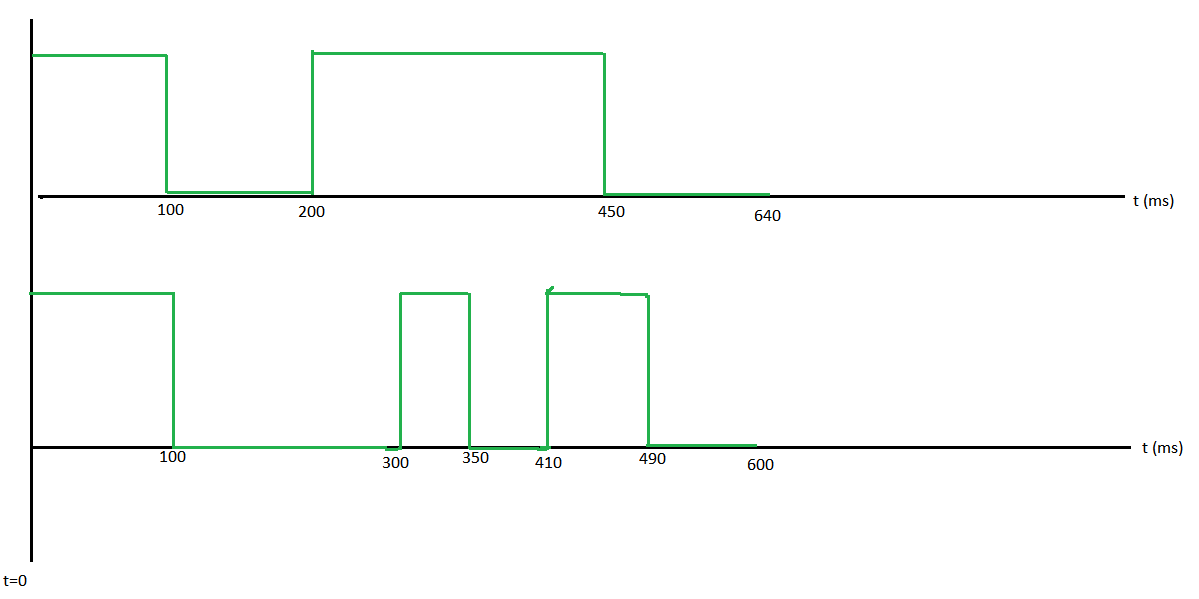
The problem is, I cannot figure out exactly what to do and in what order to make all this work.   I **think** I have to run Timer A in Continuous mode, and update TACCR0 in the ISR.    The example that comes with this MSP430 Launchpad is woefully inadequate as it only shows a single frequency at 50% duty cycle.   This I can do easily.    I have not been able to tie in all the information about "Timer_A" and "Timer0_A3" along with interrupt vector information for various CCRx registers, it is too complicated to unravel without some kind of code example. 

(1) As an expert in MSP430 timer modules, how would you approach this problem?  How would the code be structured?

(2) I am worried about ISR latency.   These pulses must always occur at the same exact time, every repeating cycle.   There cannot be an extra clock cycle or two added to the strict timing due to CCR0 updating within the ISR.  Perhaps I am mistaken on how this is supposed to be done.  In "Use of Continuous Mode" of the Timer_A datasheet section it is stated  " IN this usage, the time interval is controlled by hardware, not software, without impact from interrupt latency."    I do not understand this at all, because modifying/adding to TACCR0 in the ISR is indeed "control by software"   What is the explanation behind this?  Are the other modes, Up, Continuous, etc.   different and suffer from software controlled latency?   If so how and why are they different? 

  • Is the processor doing anything else? You can always set up a timer tick (like the arduino "millis()" ) and just bit-bang the GPIO's in whatever order you want.
  • First, you must accept the fact that every clock has jitter. In reality, nothing is perfect.
    Second, ISR latency should be calculated into the clock. So, if you need a logic 1 for 1ms (+/- some error) and the interrupt latency is 10us (+/- some error), then you must make sure your logic 1 time is 990us so that the total is 1ms (+/- some error).
    Third, you are not clear about what "arbitrary" here means. will the "arbitrary" wave forms repeat? or will they never repeat?

    If they will not repeat, then it is just a matter of generating random numbers for the timer and changing the output. if this is the case and if you need to establish known boundaries for the randomness, then your random number generation method must be implemented such that it takes the same number of cycles to complete. If you do not need to establish known boundaries, then you number generation method can vary and you could consider that as part of the randomness.

    If however they need to repeat, you will need to pre-generate the signal vector and then feed that to the timer.

    Regards,
    -Mike
  • I have code up and working mostly the way I want it to be.  Some taken directly from TI's example, some written by me.  I want to update this thread in case anyone else needs this in the future.   For the time being I have an FR4133 running with this code below, but intention was to have it run on FR5739 in the end application. 

    #include <msp430fr4133.h>
    #include <main.h>
    
    // Timer A is setup for 2us tick time
    // pulseTiming[] is a global & holds # of ticks for high/low alternating unsigned int pulseTiming[8] = {10,10,20,20,30,30,40,40};
    // Keep numEdges updated to same # of entries in pulseTiming;
    // cannot find a way to dynamically update this value other than
    // hard-coding it below. volatile unsigned int numEdges = 8;
    // Keep track of where we are in the repeating pulse loop volatile unsigned int pulseIdx = 0; int main(void) { WDTCTL = WDTPW | WDTHOLD; // Stop watchdog timer P1DIR |= BIT5; // Set P1.5 as an output, scope on this initClock(); initTimerA(); enableConfig(); __bis_SR_register(GIE); // Enable global interrupts while(1) { // MCU is alive signal P1OUT ^= BIT0; __delay_cycles(4000000); } }//main() void initClock(void) { P4SEL0 |= BIT1 | BIT2; // set XT1 pin as second function do { CSCTL7 &= ~(XT1OFFG | DCOFFG); // Clear XT1 and DCO fault flag SFRIFG1 &= ~OFIFG; } while (SFRIFG1 & OFIFG); // Test oscillator fault flag __bis_SR_register(SCG0); // disable FLL CSCTL6 |= XT1DRIVE_3; // Set XT1 driver to highest strenth? CSCTL3 |= SELREF__XT1CLK; // Set XT1CLK as FLL reference source CSCTL0 = 0; // clear DCO and MOD registers CSCTL1 &= ~(DCORSEL_7); // Clear DCO frequency select bits first CSCTL1 |= DCORSEL_3; // Set DCO = 8MHz CSCTL2 = FLLD_0 + 243; // DCODIV = 8MHz __delay_cycles(3); __bic_SR_register(SCG0); // enable FLL while(CSCTL7 & (FLLUNLOCK0 | FLLUNLOCK1)); // Poll until FLL is locked CSCTL4 = SELMS__DCOCLKDIV | SELA__XT1CLK; // Set ACLK = XT1CLK = 32768Hz // DCOCLK = MCLK and SMCLK source CSCTL5 |= DIVM_0 | DIVS_1; // MCLK = DCOCLK = 8MHZ, // SMCLK = MCLK/2 = 4MHz P1DIR |= BIT0 + BIT4; // set MCLK and LED pin as output P1SEL0 |= BIT4; // set MCLK pin as second function P8DIR |= BIT0 | BIT1; // set ACLK and SMCLK pin as output P8SEL0 |= BIT0 | BIT1; // set ACLK and SMCLK pin as second function }//initClock() void initTimerA(void){ TA0CCTL0 |= CCIE; // TACCR0 interrupt enabled TA0CCR0 = pulseTiming[0]; // Initialize first time to [0]th value of ticks TA0EX0 = TAIDEX_7; // TimerA clock source SMCLK@4MHZ / 8 >>> TimerA ticks every 2us TA0CTL |= TASSEL__SMCLK | MC_2 ; // TimerA sourced from SMCLK, Continuous Mode }//initTimerA() void enableConfig(void) { PM5CTL0 &= ~LOCKLPM5; // Disable the GPIO power-on default high-impedance mode // to activate previously configured port settings } // Timer A0 interrupt service routine #if defined(__TI_COMPILER_VERSION__) || defined(__IAR_SYSTEMS_ICC__) #pragma vector = TIMER0_A0_VECTOR __interrupt void Timer_A (void) #elif defined(__GNUC__) void __attribute__ ((interrupt(TIMER0_A0_VECTOR))) Timer_A (void) #else #error Compiler not supported! #endif { P1OUT ^= BIT5; // FIGURE OUT OVERHEAD OF THIS LINE... if(pulseIdx < numEdges - 1) { pulseIdx++; } // ... AND THIS LINE ... else { pulseIdx = 0; } // ... AND THIS LINE ... ??? TA0CCR0 += pulseTiming[pulseIdx]; // Finally, update TA0CCR0 to next value }

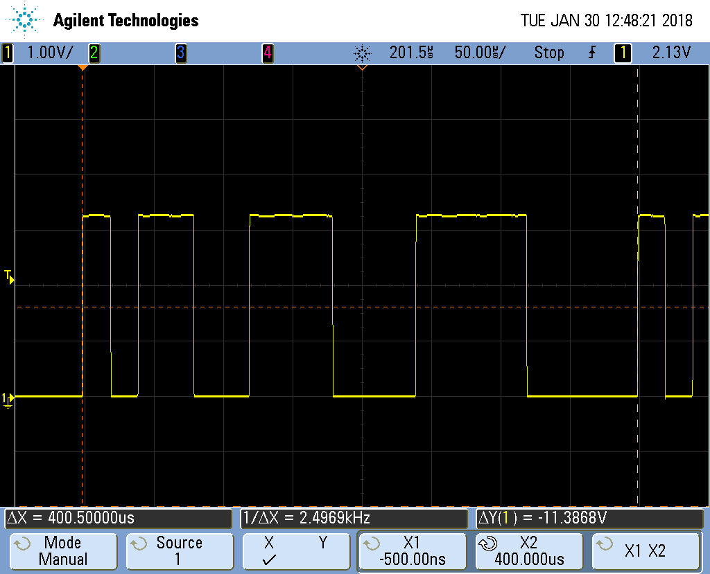
    The above code generates the following waveform.  As you can see, the first pulse high/low time is as expected ( 20us ) and the entire pattern repeats indefinitely every 400us ( 2nd screenshot below )  So I think I am mostly there ... but in the ISR above, the lines indicated in the comments are what I need to figure out the interrupt latency for, correct? 

    If so, how would I adjust this timing in light of the fact that my TimerA is much longer than MCLK (   SMCLK = MCLK/2;    SMCLK/8 )?   MCLK has a period of 125ns  but the resolution of TimerA is 2us.   Is there a mechanism to achieve this correction factor?  Thank you for your input.

  • I have code up and working mostly the way I want it to be.  Some taken directly from TI's example, some written by me.  I want to update this thread in case anyone else needs this in the future.   For the time being I have an FR4133 running with this code below, but intention was to have it run on FR5739 in the end application.

    #include <msp430fr4133.h>

    #include <main.h>

    // Timer A is setup for 2us tick time

    // pulseTiming[] is a global & holds # of ticks for high/low alternating

    unsigned int pulseTiming[8] = {10,10,20,20,30,30,40,40};

    // Keep numEdges updated to same # of entries in pulseTiming;

    // cannot find a way to dynamically update this value other than

    // hard-coding it below.

    volatile unsigned int numEdges = 8;

    // Keep track of where we are in the repeating pulse loop

    volatile unsigned int pulseIdx = 0;

    int main(void)

    {

       WDTCTL = WDTPW | WDTHOLD;               // Stop watchdog timer

       P1DIR |= BIT5;                          // Set P1.5 as an output, scope on this

       initClock();

       initTimerA();

       enableConfig();

       __bis_SR_register(GIE);                 // Enable global interrupts

       while(1)

       {

                                               // MCU is alive signal

           P1OUT ^= BIT0;

           __delay_cycles(4000000);

       }

    }//main()

    void initClock(void)

    {

       P4SEL0 |= BIT1 | BIT2;                  // set XT1 pin as second function

       do

       {

         CSCTL7 &= ~(XT1OFFG | DCOFFG);      // Clear XT1 and DCO fault flag

         SFRIFG1 &= ~OFIFG;

       } while (SFRIFG1 & OFIFG);              // Test oscillator fault flag

       __bis_SR_register(SCG0);                // disable FLL

       CSCTL6 |= XT1DRIVE_3;                   // Set XT1 driver to highest strenth?

       CSCTL3 |= SELREF__XT1CLK;               // Set XT1CLK as FLL reference source

       CSCTL0 = 0;                             // clear DCO and MOD registers

       CSCTL1 &= ~(DCORSEL_7);                 // Clear DCO frequency select bits first

       CSCTL1 |= DCORSEL_3;                    // Set DCO = 8MHz

       CSCTL2 = FLLD_0 + 243;                  // DCODIV = 8MHz

       __delay_cycles(3);

       __bic_SR_register(SCG0);                // enable FLL

       while(CSCTL7 & (FLLUNLOCK0 | FLLUNLOCK1)); // Poll until FLL is locked

       CSCTL4 = SELMS__DCOCLKDIV | SELA__XT1CLK;  // Set ACLK = XT1CLK = 32768Hz

                                                  // DCOCLK = MCLK and SMCLK source

       CSCTL5 |= DIVM_0 | DIVS_1;                 // MCLK = DCOCLK = 8MHZ,

                                                  // SMCLK = MCLK/2 = 4MHz

       P1DIR |= BIT0 + BIT4;                   // set MCLK and LED pin as output

       P1SEL0 |= BIT4;                         // set MCLK pin as second function

       P8DIR |= BIT0 | BIT1;                   // set ACLK and SMCLK pin as output

       P8SEL0 |= BIT0 | BIT1;                  // set ACLK and SMCLK pin as second function

    }//initClock()

    void initTimerA(void){

       TA0CCTL0  |= CCIE;                            // TACCR0 interrupt enabled

       TA0CCR0    = pulseTiming[0];                  // Initialize first time to [0]th value of ticks

       TA0EX0     = TAIDEX_7;                        // TimerA clock source SMCLK@4MHZ / 8  >>>  TimerA ticks every 2us

       TA0CTL    |= TASSEL__SMCLK | MC_2  ;          // TimerA sourced from SMCLK, Continuous Mode

    }//initTimerA()

    void enableConfig(void)

    {

       PM5CTL0 &= ~LOCKLPM5;                   // Disable the GPIO power-on default high-impedance mode

                                               // to activate previously configured port settings

    }

    // Timer A0 interrupt service routine

    #if defined(__TI_COMPILER_VERSION__) || defined(__IAR_SYSTEMS_ICC__)

    #pragma vector = TIMER0_A0_VECTOR

    __interrupt void Timer_A (void)

    #elif defined(__GNUC__)

    void __attribute__ ((interrupt(TIMER0_A0_VECTOR))) Timer_A (void)

    #else

    #error Compiler not supported!

    #endif

    {  

       P1OUT ^= BIT5;                                 // FIGURE OUT OVERHEAD OF THIS LINE...

       if(pulseIdx < numEdges - 1) { pulseIdx++;   }  // ... AND THIS LINE ...

       else                        { pulseIdx = 0; }  // ... AND THIS LINE ... ???

       TA0CCR0 += pulseTiming[pulseIdx];              // Finally, update TA0CCR0 to next value

    }

    The above code generates the following waveform.

    As you can see, the first pulse high/low time is as expected ( 20us ), subsequent high/low times are as I expect, and the entire pattern repeats indefinitely every 400us ( 2nd screenshot  showing X1/X2 at the beginning/end of pattern)  at the correct period.   So I think I am mostly there ...

    ... but in the ISR code above, the lines indicated in the comments are what I need to figure out the interrupt latency for, correct?

    If so, how would I adjust this timing in light of the fact that my TimerA is much longer than MCLK (   SMCLK = MCLK/2;    SMCLK/8 )?   MCLK has a period of 125ns  but the resolution of TimerA is 2us.   Is there a mechanism to achieve this correction factor?  Thank you for your input.

**Attention** This is a public forum