Part Number: MSP430FR2000
Tool/software: Code Composer Studio
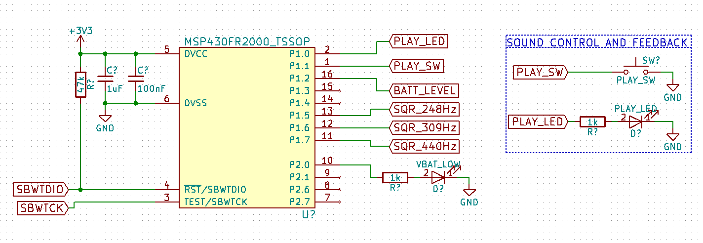
To better learn programing the MSP430 series of microcontrollers I jumped head first into a side project with the MSP430FR2000. The goal is to be able to produce a musical chord that mimics a train horn (for silly reasons). The final circuit will be battery powered so that I can attach it to a paging speaker that was destined to be discarded.
To generate the sound I am using Timer_B (the only timer on the microcontroller) to generate the three different frequencies. I followed TI app note SLAA513A for generating the three different frequencies. I have a button attached to P1.1 that generates an interrupt to start Timer_B and the frequency generation until Timer_B overflows at which point the sound shuts off. The frequencies are generated on IO pins P1.5 to P1.7. I have an LED attached to P1.0 to indicate when sound is being generated for debug purposes right now.
Surprisingly I got the frequency generation part of the code working very quickly. The part I ran into trouble is when I went to used the eCOMP to monitor the battery voltage. The final circuit will have the battery voltage connect to a voltage divider whose output is connected to the IO pin P1.2 on the MSP430. This is the C2 input for the V+ of the comparator. The V- of the comparator is connect to the the internal DAC that is referenced from the internal voltage reference. The output of the comparator is connected to IO pin P2.0/COUT that will illuminate a LED when the battery voltage reaches a certain level.
I cannot get the output of the comparator to illuminate the LED. During debug I am setting P1.2 using a wire that I connect to GND and 3.3V but the comparator will not toggle. Using CCS in debug mode I can see CPOUT toggle in the CPCTL1 register but that does not seem to toggle P2.0. I can measure using a DMM a very small increase of ~10mV on P2.0 when P1.2 is connected to GND. Also when P1.2 is connected to GND (ie CPOUT is 1) frequency is not generated at P1.6 and P1.7.
Using the same circuit setup I modified the TI example msp430fr211x_eCOMP_01.c with the same settings as my code and can get the comparator to work (Timer_B is not in use).
There seems to be an issue with using the comparator and Timer_B. Is there a register setting that I overlooked that has connected the two together? In the User's Guide figure 17-1 shows the comparator has an output to Timer CPTM but searching the pdf for CPTM reveals this is the only mention of CPTM. Does this mean that the output of the comparator is connected to Timer_B?
I am hoping that it is something obvious that I have overlooked. Any help would be appreciated. Thanks.
//******************************************************************************
//  MSP430FR2000 - Train Horn
//
//  Description: Toggle pins at multiple frequencies using only TimerB,
//  mimic train horn for silly reasons.
//  P1.5 toggles using CRR0 and software. P1.6 and P1.7 toggle using CCR1 and CCR2
//  Button on P1.1 enables frequency generation until TimerB overflows
//  eCOMP to monitor Vbat (not setup currently, test mode only)
//
//  ACLK = TBCLK = 32768Hz, MCLK = SMCLK = default DCODIV ~1MHz
//  P1.5 = CCR0 ~ 32KHz/(2*66) = ~248.24Hz -> target frequency: 246.94Hz (B3)
//  P1.6 = CCR1 ~ 32KHz/(2*53) = ~309.13Hz -> target frequency: 311.13Hz (D#4)
//  P1.7 = CCR2 ~ 32KHz/(2*37) = ~442.81Hz -> target frequency: 440.00Hz (A4)
//
//                MSP430FR2000
//             -----------------
//         /|\|             P1.0|--> LED for timer status
//          | |             P1.1|<-- Button to gnd
//          | |          P1.2/C2|<-- V+ eCOMP input
//          | |             P1.5|--> ~248.24Hz
//          --|RST    P1.6/TB0.1|--> ~309.13Hz
//            |       P1.7/TB0.2|--> ~442.81Hz
//            |        P2.0/COUT|--> LED eCOMP status
//
//
//   TimerB multifrequency based on TI app note SLAA513A and accompanying code
//******************************************************************************
#include <msp430.h>

int main(void)
{
    WDTCTL = WDTPW | WDTHOLD;                   // Stop WDT

    // Configure reset
    SFRRPCR |= SYSRSTRE | SYSRSTUP;             // Enable internal pullup resistor on reset pin

    // Configure Comparator input & output
    P1SEL0 |= BIT2;                             // Select eCOMP input function on P1.2/C2
    P1SEL1 |= BIT2;
    P2DIR  |= BIT0;                             // Select CPOUT function on P2.0/COUT
    P2SEL1 |= BIT0;

    // Configure Interrupt Button
    P1IES  |= BIT1;                             // play button interrupts on high-to-low transition
    P1REN  |= BIT1;                             // enable resistor, must set P1OUT for pullup
    P1OUT  |= BIT1;

    // Configure Timer_B Outputs
    P1SEL1 |= BIT6 | BIT7;                      // select TB0.1 and TB0.2 pin functions for P1.6 and P1.7
    P1DIR  |= BIT0 | BIT5 | BIT6 | BIT7;        // P1.0, P1.5, P1.6, and P1.7 outputs
    P1OUT  &= ~BIT0;                            // turn off LED on P1.0

    // Configure Unused GPIO
    P1DIR |= BIT3 | BIT4;
    P2DIR |= BIT1 | BIT6 | BIT7;

    PM5CTL0 &= ~LOCKLPM5;                       // Disable the GPIO power-on default high-impedance mode to activate
                                                // previously configured port settings

    // Configure reference
    PMMCTL0_H = PMMPW_H;                        // Unlock the PMM registers
    PMMCTL2 |= INTREFEN;                        // Enable internal reference
    while(!(PMMCTL2 & REFGENRDY));              // Poll till internal reference settles

    // Setup eCOMP
    CPCTL0 |= CPPSEL1;                          // Select C2 as input for V+ terminal
    CPCTL0 |= CPNSEL1 | CPNSEL2;                // Select DAC as input for V- terminal
    CPCTL0 |= CPPEN | CPNEN;                    // Enable eCOMP input
    CPDACCTL |= CPDACREFS | CPDACEN;            // Select on-chip VREF and enable DAC
    CPDACDATA |= 0x0020;                        // CPDACBUF1=On-chip VREF *32/64 = 0.75V
    CPCTL1 |= CPEN | CPMSEL | CPINV;            // Turn on eCOMP, in low power mode, inverted output*/

    P1IFG = 0;                                  // clear any pending interrupts
    P1IE = BIT1;                                // enable interrupts on P1.1

    for(;;) {
        __bis_SR_register(LPM3_bits | GIE);     // Enter LPM3, enable interrupts
        __no_operation();                       // For debug
    }
}
// Port1 Interrupt Vector handler
#pragma vector=PORT1_VECTOR
__interrupt void PORT1_ISR(void)
{
    P1IE = 0;                                   // disable any further interrupts
    P1OUT ^= BIT0;                              // toggle P1.0 LED for timer_b status

    // setup timerB
    TB0CCTL0 = OUTMOD_4 + CCIE;                 // TBCCR0 toggle, interrupt enabled
    TB0CCTL1 = OUTMOD_4 + CCIE;                 // TBCCR1 toggle, interrupt enabled
    TB0CCTL2 = OUTMOD_4 + CCIE;                 // TBCCR2 toggle, interrupt enabled
    TB0CTL = TBSSEL_1 | MC_2 | TBCLR | TBIE;    // ACLK, continuous mode, clear TBR, enable interrupts
}

// Timer0_B3 Interrupt Vector (TBIV) handler
#pragma vector=TIMER0_B0_VECTOR
__interrupt void TIMER0_B0_ISR(void)
{

    TBCCR0 += 66;
    P1OUT ^= BIT5;                              // ~248.24Hz frequency generation on P1.5
}

// Timer0_B3 Interrupt Vector (TBIV) handler
#pragma vector=TIMER0_B1_VECTOR
__interrupt void TIMER0_B1_ISR(void)
{
    switch(__even_in_range(TB0IV,TB0IV_TBIFG))
    {
        case TB0IV_NONE:
            break;                              // No interrupt
        case TB0IV_TBCCR1:                      // CCR1
            TBCCR1 += 53;                       // ~309.13Hz frequency generation on P1.6
            break;
        case TB0IV_TBCCR2:                      // CCR2
            TBCCR2 += 37;                       // ~442.81Hz freguency generation on P1.7
            break;
        case TB0IV_TBIFG:                       // overflow
            P1OUT    ^= BIT0;                   // toggle P1.0 LED for timer_b status
            TB0CTL   &= ~(MC_2);                // disable Timer_B
            TB0CCTL0 = 0;                       // disable CCR0, CCR1, CCR2
            TB0CCTL1 = 0;
            TB0CCTL2 = 0;
            P1OUT    &= ~(BIT5 | BIT6 | BIT7);  // set pins low since they could have been high during interrupt

            // enable play button again
            P1IFG = 0;                          // acknowledge all interrupts
            P1IE  = BIT1;                        // enable interrupt on P1.1
            break;
        default:
            break;
    }
}