This thread has been locked.

If you have a related question, please click the "Ask a related question" button in the top right corner. The newly created question will be automatically linked to this question.

RTOS/SIMPLELINK-MSP432-SDK: Using RTC to trigger an event every 6 hours instead of watchdog

Part Number: SIMPLELINK-MSP432-SDK
Other Parts Discussed in Thread: ENERGYTRACE, TPS22810

Tool/software: TI-RTOS

Hi Team,

My application at present triggers an event every 6 hours and once that event is completed it registers the time with the data in the file on SD card.

At the moment we are using watchdog to execute this task.

However, the limitation of using watchdog is that we cannot put the unit in the deep sleep mode.

And in order to utilize the feature of deep sleep we have to use the RTC (real time clock).

Please can someone share information on how to trigger the RTC every 6 hours so as we can trigger the event and also once the event has accomplished how can we get the real time to be written into the SD card for the file written?

I have went through the forum and the document and also the header file "rtc_c.h" but it only shows how we can trigger every minute or every hour certain minute pass the hour.

For us, whenever we start the unit (msp432) every 6 hours after the start of the unit, the rtc should trigger the event and we need to get the time at the rtc triggered.

I am using the SimpleLink MSP432 SDK RTOS version.

  • Vikram,

       The energy trace measures the current draw on the 3.3V pin on the XDS110 side of the launchpad.  On the XDS110 there is an MSP430 device which is counting the PWM pulses of the regulator and calculating the power/current.  Your target must be sourced from this rail in order to use the energy trace function.  

    In other words, you would only connect pins 2 and 6 to the device under test.  I would recommend removing the battery and all other power sources from the DUT before applying 3.3V via the launchpad.  

    Additionally, the JTAG connection should be removed as these pins will provide a leakage path back to the XDS110 processor and invalidate your current measurements.

    Please let me know if this is not clear.

    Regards,

    Chris

  • Hi Chris,

    Thank you for the reply.

    So what you mean to say that I do not keep the 3.6V D cell battery mounted on the board use the VCC and GND of Launchpad to power 3.3V to the target board?

    So do I connect the jumper that is at GND and the VCC pins of J101 while powering the Launchpad and having it connected to debugger through JTAG?

    Since the msp432 MCU chip is on the target board and the only way to connect it to debugger is through the JTAG cable with one end of the cable connected to the taget board and the another end on the J102 side of Launchpad which is connected to the PC CCS debugger.

    Is the image below correct for connection?

    Please correct me if I am wrong.

    Thank you

    Vikram

  • Vikram,
    What are you trying to measure? I see three different possibilities:

    (1) You are trying to measure the power consumption of the MSP432P on the launchpad. The current picture you are showing will do this. The jtag connection serves no purpose and can be removed.
    (2) You are trying to measure the power consumption of the entire green board, the MSP432 and all other circuits on the 3.3V rail. If this is the case then you would need to remove the jumpers that you have on the MSP432 launchad and use wires to connect the XDS110 side of the launchpad, 3.3V and GND only, to your board. In doing this you will be measuring the consumption of the entire board. Please ensure it is within the limits of the launchpad. The JTAG connection serves no purpose and can be removed.
    (3) You are trying to measure the power consumption of the MSP432 only on your board. Similar to '2' you will need to bring over the 3.3V and GND connections from the XDS110 side of the launchpad . You will need to isolate the other circuits so that only the MSP432 is connected to the 3.3V rail. The JTAG connection serves no purpose and can be removed.

    Regards,
    Chris
  • Thank you Chris.

    So I am trying to measure the 2nd point the power consumption of entire board when the msp432 is active and when it goes into sleep.
    When you mentioned connecting wires from XDS110 side of launchpad, 3.3V and GND only to the board you mean connecting those ends to the battery terminal slot? I mean instead of having the battery connected, I connect the 3.3V of XDS110 to positive of battery holder and the GND to the negative side of battery holder?
    And I remove the JTAG, then how will it show me the measurements in the EnergyTrace since as per the earlier document that you had sent to refer to use the EnergyTrace it mentions to initially run in the "Free run" and then switch to the EnergyTrace mode by simply disconnecting the target?

    Sorry if I am confusing you.

    Vikram
  • Ok I got what you were mentioning Chris.

    I used that approach. Below is the image for the set up.

    But using this setup the minimum current that I am getting is 17.7319 mA which does not seem correct since using the multimeter in series across the battery and using the battery supply I am getting 2.36 mA in deep sleep mode.

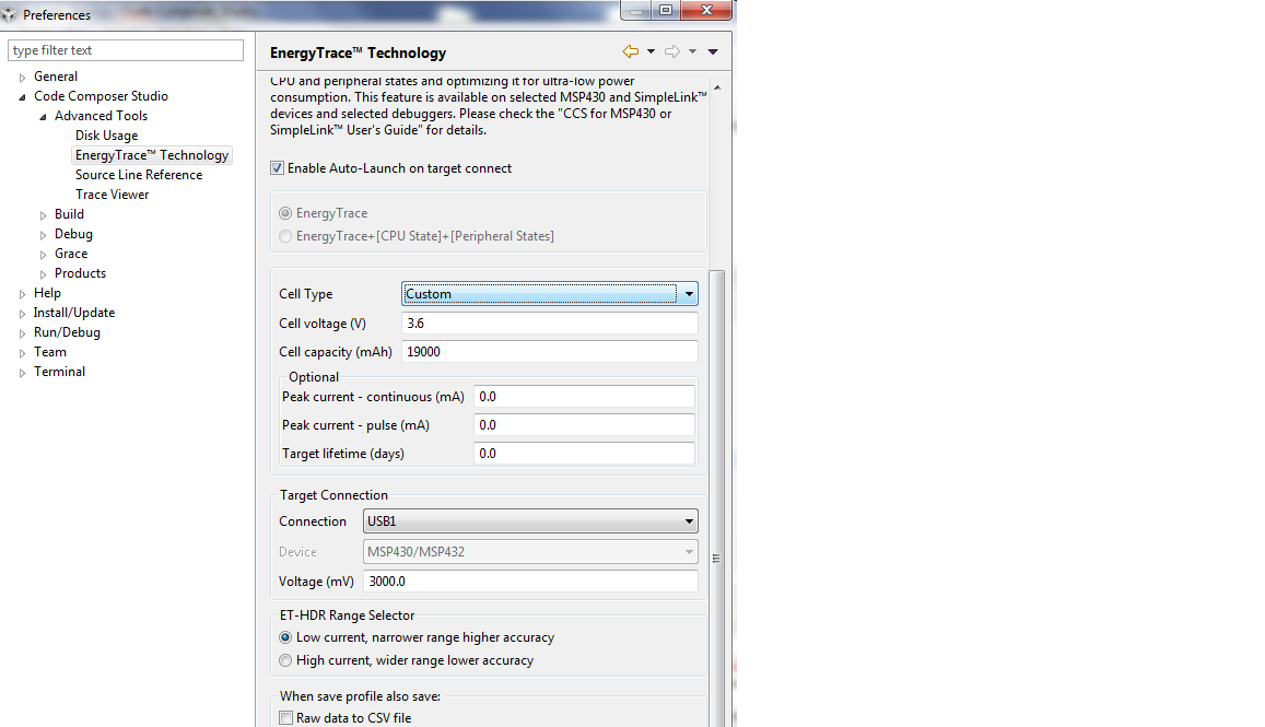
    And the settings that I have used in the EnergyTrace window is as below.

    Can you suggest why this would be showing such a high value in deep sleep mode?

    Vikram

  • Also Chris one more thing if you can confirm is about the voltage on the VSW pin on the MCU when the MCU is in deep sleep mode. What should be the voltage at the VSW pin showing as? At my end I get is 1.43V in the even that MCU is in deep sleep mode.
  • Vikram,

        Do you know if the current you are measuring is isolated to the MSP432 or if there are additional circuits on the 3.3V supply from the launchpad?  I would make an account of all devices on the rail.  I do not know if this is related but I had a similar issue with an LDO that I did not account for and was actually applying the voltage from the launchpad on the input of the MSP432 but also the output of the LDO.  

        The VSW is connected to the internal DCDC converter.  Are you using that or the LDO?  In lpm3 (deep sleep) the DCDC converter is turned off.  In order to go to LPM3 the core voltage must be transitioned from the DCDC to the LDO.  This should be handled by the driver.  The ~1.4 volts is in line with the Vcore '1' setting. 

    Please refer to section 8.5 of the TRM and TABLE 5-19 in the datasheet.

    Regards,

    Chris 

  • Thank you for the reply Chris,

    I am not 100% sure about the first part that you have mentioned but as per my understanding from the schematics I see that yes there are other circuits which are getting 3V3 voltages such as there are couple of switching circuits (TPS22810) whose output controls the voltage supplied to SD card and the uPulser. The input to these parts are from the same rail.

    I am using the active mode as DCDC_VCORE1 and for the sleep mode I am using the LPM3 mode.

    So as per you mentioned, the power driver should convert from DCDC to LDO mode in order for the circuit to go into Deep sleep (LPM3)? How do I verify this?

    Also unfortunately, the TRM that I have does not have a section 8.5 (Can you tell me what topic it is to refer please? And the table 5-19 refers to current consumption in DC-DC based LPM0 Mode but in the deep sleep it should be LPM3?

    Sorry to bother a lot.

    Vikram

  • Vikram,
    I cannot think of a good way to verify the drivers. The source code is provided and there are examples available which demonstrate using the drivers and achieving LPM3 numbers which are consistent with the datasheet. I think the simplest verification is to put the code on a launchpad, isolating the MSP432 from the other circuits, and confirm LPM operation.

    Section 8.5 of the TRM is the section on the Power Control Manager. I think you have confused section 5.19 with table 5-19. Please refer to this thread.
    e2e.ti.com/.../2523099

    Chris

  • Vikram,
    Thank you for contributing to such a long and informative thread. I am very hopeful that the dialog will be useful to the larger community. In hind-site, I think it would be more beneficial to break the individual topics into distinct threads/discussions, but regardless there is still a lot of good content.

    I know this did not provide the resolution you had hoped for, but again this discussion has been very valuable and helps me to provide feedback to the larger team developing the SDK.

    Best Regards,
    Chris
  • I appreciate Chris your effort and also would like to thank Darren who did provide his input into troubleshooting the current leakage issue resolution.

**Attention** This is a public forum