This thread has been locked.

If you have a related question, please click the "Ask a related question" button in the top right corner. The newly created question will be automatically linked to this question.

MSP430FR5994: ADC external input clock at the same freqency (timer in pass through mode)

Part Number: MSP430FR5994

Hi,

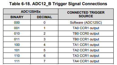
I have a problem to put the output of TIMER_A to the same frequency as external INCLK, as it should feed ADC sampling period. The clock is always divided to at least to number of two.

Thanks,

Alexey

  • Thank you Alexey for reaching out to us with your question regarding the MSP430FR5994.

    From your description it appears you are providing an external clock to the TIMER_A and using this timer to trigger the ADC sampling, but you are seeing this sampling period to be 1/2 of our INCLK frequency.

    Can you tell me what values you are using for all the TIMER_A registers.
    Also, can you tell me what values you are using for ADC12CTL0, ADC12CTL1 registers?
  • Hi Dennis,

    I'm using the working one:
    TA0CCR0 = 1;
    TA0CCTL0 = OUTMOD_0;
    TA0CCR1 = 1;
    TA0CCTL1 = OUTMOD_3;
    TA0CTL = TASSEL__INCLK + TACLR;
    But I want to be worked this one as a pass-through mode:
    TA0CCR0 = 0;
    TA0CCTL0 = OUTMOD_0;
    TA0CCR1 = 0;
    TA0CCTL1 = OUTMOD_0;
    TA0CTL = TASSEL__INCLK + TACLR;
    But the second scenario seems to be unsupported by hardware.
    ADC regs:
    ADC12CTL0 = ADC12SHT0_2 | ADC12SHT1_2 | ADC12ON;
    ADC12CTL1 = ADC12SHP | ADC12SHS_1 | ADC12CONSEQ_2 | ADC12SSEL_3;

    If it even possible to feed the output signal of TA0.1 from exernal pin, it would be nice.

    Thanks,
    Alexey
  • I'm not sure I fully understand your last comment. The TA0.1 pin is an output when configured with one of the timer's output modes. When you say "feed the output signal of TA0.1 from external pin", do you mean you want to drive the TA0.1 with another external pin?
  • I need to make possible ADC sampling period equal external clock frequency. (Using even tricks or so.) Nothing more.
    Regards,
    Alexey
  • Ok, got it.

    Unfortunately, there is no way to trigger the ADC12 directly from an external trigger (clock) input.

    It is possible to use a GPIO pin with an interrupt to respond to the external trigger and in the the ISR handler you could set the ADC12SC (software controlled start conversion bit).  Of course it will take a few processor instruction cycles to execute the jump and code to set the bit, but it will be deterministic (take same amount of time each time) and will cause an ADC measurement at the same rate as the input trigger, just slightly delayed.

  • Dennis Lehman said:
    It is possible to use a GPIO pin with an interrupt to respond to the external trigger and in the the ISR handler


    I understand it.

    Unfortunately, the clock input is quite high (128 kHz), so the for real-time process this is not a case since there are many other interrupts, some of them with higher priority level.

    But thank you for your feedback,
    Alexey

**Attention** This is a public forum