This thread has been locked.
If you have a related question, please click the "Ask a related question" button in the top right corner. The newly created question will be automatically linked to this question.
Hi there,
Occasionally my MSP430FR5739 seems to miss a falling edge interrupt on P1.4.
Is there any errata covering the cause of this and any mitigating factors?
It causes a lot of trouble as P1.4 is being used to bit bang in this situation and timing is sensitive.
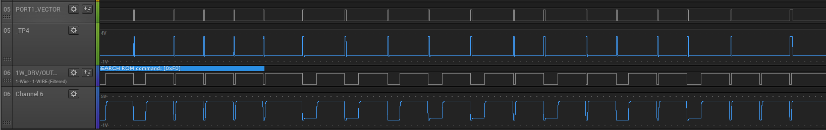
To the far right hand side you will notice the _TP4 line never is set high when Channel 06 receives its second to last falling edge.
The PORT1_VECTOR's first instruction is to set the output bit to 1 for P1OUT[3] (_TP4). It's last instruction is to clear it. It has no mechanism to return from the ISR early. Therefore _TP4 indicates the duration of the PORT1_VECTOR. High means inside the vector, low means outside of it.
P1IE[4] is set high once and never accessed again.
P1IES[4] is also set high once and never accessed again.
The selection bits are set once, and never unset or modified. The direction bits, are set once and never unset or modified. REN is never set, and OUT is never set for the associated bit in the respective registers.
Channel 06 is the line connected to P1.4 and is pulled-up. When the MSP430 pulls this down, it approaches 0.3V which you may be able to see on the analogue (bottom) line, the master device pulls it to zero.
So what's going on? Is there something causing the chip to miss the interrupt? It is kind of vital. Is there some probability an interrupt will be missed?
Voltages are 0.00-4.00V on the Channel 06 port (P1.4) as an input and the other line (_TP4) is associated with PJ.3 as an output and physically only connected to the probe.
Hi Matthew,
Could you please share your code or you can check your code with this example code.
/* --COPYRIGHT--,BSD_EX * Copyright (c) 2012, Texas Instruments Incorporated * All rights reserved. * * Redistribution and use in source and binary forms, with or without * modification, are permitted provided that the following conditions * are met: * * * Redistributions of source code must retain the above copyright * notice, this list of conditions and the following disclaimer. * * * Redistributions in binary form must reproduce the above copyright * notice, this list of conditions and the following disclaimer in the * documentation and/or other materials provided with the distribution. * * * Neither the name of Texas Instruments Incorporated nor the names of * its contributors may be used to endorse or promote products derived * from this software without specific prior written permission. * * THIS SOFTWARE IS PROVIDED BY THE COPYRIGHT HOLDERS AND CONTRIBUTORS "AS IS" * AND ANY EXPRESS OR IMPLIED WARRANTIES, INCLUDING, BUT NOT LIMITED TO, * THE IMPLIED WARRANTIES OF MERCHANTABILITY AND FITNESS FOR A PARTICULAR * PURPOSE ARE DISCLAIMED. IN NO EVENT SHALL THE COPYRIGHT OWNER OR * CONTRIBUTORS BE LIABLE FOR ANY DIRECT, INDIRECT, INCIDENTAL, SPECIAL, * EXEMPLARY, OR CONSEQUENTIAL DAMAGES (INCLUDING, BUT NOT LIMITED TO, * PROCUREMENT OF SUBSTITUTE GOODS OR SERVICES; LOSS OF USE, DATA, OR PROFITS; * OR BUSINESS INTERRUPTION) HOWEVER CAUSED AND ON ANY THEORY OF LIABILITY, * WHETHER IN CONTRACT, STRICT LIABILITY, OR TORT (INCLUDING NEGLIGENCE OR * OTHERWISE) ARISING IN ANY WAY OUT OF THE USE OF THIS SOFTWARE, * EVEN IF ADVISED OF THE POSSIBILITY OF SUCH DAMAGE. * ******************************************************************************* * * MSP430 CODE EXAMPLE DISCLAIMER * * MSP430 code examples are self-contained low-level programs that typically * demonstrate a single peripheral function or device feature in a highly * concise manner. For this the code may rely on the device's power-on default * register values and settings such as the clock configuration and care must * be taken when combining code from several examples to avoid potential side * effects. Also see www.ti.com/grace for a GUI- and www.ti.com/msp430ware * for an API functional library-approach to peripheral configuration. * * --/COPYRIGHT--*/ //****************************************************************************** // MSP430FR57xx Demo - Software Port Interrupt Service on P1.4 from LPM4 // // Description: A Lo/Hi transition on P1.4 will trigger P1ISR the first time. // On hitting the P1ISR, device exits LPM4 mode and executes section of code in // main() which includes toggling an LED and the P1.4IES bit which switches between // Lo/Hi and Hi/Lo trigger transitions to alternatively enter the P1ISR. // ACLK = n/a, MCLK = SMCLK = default DCO // // MSP430FR5739 // ----------------- // /|\| |- // | | | // --|RST |- // /|\ | | // --o--|P1.4 P1.0|-->LED // \|/ // // Priya Thanigai // Texas Instruments Inc. // August 2010 // Built with IAR Embedded Workbench Version: 5.10 & Code Composer Studio V4.0 //****************************************************************************** #include <msp430.h> int main(void) { WDTCTL = WDTPW + WDTHOLD; // Stop watchdog timer P1DIR |= BIT0; // Set P1.0 to output direction P1OUT &= ~BIT0; P1OUT &= ~BIT4; // P1IES &= ~BIT4; // P1.4 Lo/Hi edge P1IE = BIT4; // P1.4 interrupt enabled P1IFG &= ~BIT4; // P1.4 IFG cleared while(1) { __bis_SR_register(LPM4_bits + GIE); // Enter LPM4 w/interrupt __no_operation(); // For debugger P1OUT ^= BIT0; // P1.0 = toggle P1IE = BIT4; // P1.4 interrupt enabled } } // Port 1 interrupt service routine #if defined(__TI_COMPILER_VERSION__) || defined(__IAR_SYSTEMS_ICC__) #pragma vector=PORT1_VECTOR __interrupt void Port_1(void) #elif defined(__GNUC__) void __attribute__ ((interrupt(PORT1_VECTOR))) Port_1 (void) #else #error Compiler not supported! #endif { P1IES ^= BIT4; P1IFG &= ~BIT4; // Clear P1.4 IFG P1IE = 0; __bic_SR_register_on_exit(LPM4_bits); // Exit LPM4 }
Best regards,
Cash Hao
**Attention** This is a public forum