This thread has been locked.

If you have a related question, please click the "Ask a related question" button in the top right corner. The newly created question will be automatically linked to this question.

Display Battery life on LCD using MSP430

Other Parts Discussed in Thread: MSP430F2274

Hi,

I'm new to microcontrollers, but i've started the learning process. I built a solar lithium battery charger, and now i'm trying to display how much charge is left in the battery using microcontroller and small LCD. I have never worked with microcontrollers before I looked at MSP430 launch pad, should I buy this product? Will this be able to display battery life on small LCD and can you guys advise me what LCD should i get and i wanna keep everything 3V or low. 

Thanks


  • If you use MSP430F4xx, they are able to control LCD "glass" directly. Other MSP430, such as what are included in the LaunchPad, cannot do that and need an external LCD controller to drive the LCD "glass". In most cases, the LCD controller is glued on the back of the "glass" as an integrated part of a LCD "module". But still, the controller consumes extra power.

  • Thanks for reply, can you tell me which specific model should i order and what other components will i need to program the microcontroller.

  • Hi Amit,

    do you have a LCD at hand or do you need to buy this too? In case you don't have the LCD I recommend buying a standard 16x2 LCD module (because they are cheap and easy to use; here's an example http://www.sparkfun.com/commerce/product_info.php?products_id=9051 should be possible to get them cheaper!).

    I have some demo code in 'My Files' : http://e2e.ti.com/members/1371069/files/default.aspx for such LCDs.

    You will need to drive the LCD in 4-bit mode (SW needs to be changed) because the devices which ship with launchpad only have limited I/O.

    To have a more powerfull target MCU to play with buy one of these http://www.schmartboard.com/index.asp?page=products_so&id=58 and solder a MSP430F2274 in place. This will give you a powerfull target with plenty of I/Os to play with :o)! In addition, you can use the code as is!

    Kind regards
    aBUGSworstnightmare

  • Thanks for the information, I don't have LCD yet so i guess i'll order a launch pad and the LCD that you recommended. I saw that this LCD require 3.3V but I was thinking about using 3V battery to power up the MCU and LCD so you think it will work with 3V? And also can you tell me in detail how to install driver of that LCD on microcontroller that comes with launchpad. 

    So now im going to order launchpad and LCD module and you think with this i'll be able to display charge left in my rechargeable battery on LCD?

    Can you also tell me where I can find more example codes and programs to get started with launchpad i wasn't able to find much.

    Thanks

    Amit

  • Hi Amit,

    you should have a look at the LCDs data sheet before odering one! Keep an eye on the maximum operating voltage since Launchpad is operating at 3.6V.

    The code example will give you the basic routines for operating an standard LCD and also deals with the ADC (sampled value will be displayed on the LCD). The software was writen for MSP430F2274 but you can easily downsize it to fit into the value line parts which ship with Launchpad.

    Since you're new to MSP430 programming (and maybe even new to C language programming) you will need to sit down and take a detailed look on the code to understand it.

    Here are some more recommendations for you:

    - http://processors.wiki.ti.com/index.php/New_Project_Guides (very good guides on how to work with the IDEs and create a project)

    - http://processors.wiki.ti.com/index.php/MSP430_LaunchPad_(MSP-EXP430G2) (Launchpad wiki site)

    - http://www.ti.com/lit/zip/slac080 (code examples for value line parts; use them to get familiar with the mcicrocontroller)

    Rgds
    aBUGSworstnightmare

  • I did my research and tried to understand everything and you were rite im new to programing as well but i understand and i know i can learn. So now i'm going to order launchpad and i'm gonna use:

    MSP430G2231IN14 – 2kB Flash, 128B RAM, 10 GPIO, 1x 16-bit timer, WDT, BOR, 1x USI (I2C/SPI), 8ch 10-bit ADC

    it comes with launchpad.

    And I think it will be easy if i use LED graph display like:

    http://www.jameco.com/webapp/wcs/stores/servlet/Product_10001_10001_697477_-1

    it will be easier than using LCD to display.

    If this can do it....i'll need just little help to write a code that will light up all the LEDs when voltage from my battery is 4.2V and light up 8 LED with voltage is 3.8 and 6 when voltage is 3.6.........light up one bar when voltage is 3.0V (since its lithium battery and it outputs 3V when its dead).

    Thanks

    Amit

  • Hi Amit,

    using this bargraph LED is a ggod choice, but you will have to take care with the ADC! You mentioned you will measure your battery (LiPo, I think you want to connect the ADC to the balancer inputs) which can have 4.2V when fully charged.

    You can not do this since the maximum operating voltage for the ADC is 3.6V! So, you need to take appropriate action not to damage the chip (i.e. using a voltage divider, ..).

    If you want to use a less I/Os as possible for driving the LEDs you should have a look at this application note (Low cost tilt sensor; http://focus.ti.com/mcu/docs/mcuprodtechdoc.tsp?sectionId=95&viewType=mostuseful&tabId=1202&rootFamilyId=4&familyId=342&docTitle=tilt&docCategoryId=1). It shows how to drive 6 LEDs with only 3 I/O pins (but only one can be ON at any time).

    Rgds
    aBUGSworstnightmare

  • Hmmm this confuses me a little bit, if there are 10 bars on led bargraph i need 10 pins for output? And microcontroller in launchpad has total 14 pins and 10 ADC...this all is so confusing lol but im waiting for launchpad to arrive I've already placed the order then i'll have more idea..but u think its better (or easier) to use LED bargraph or LCD? And can you help me with code in future for that?

  • Hi Amit,

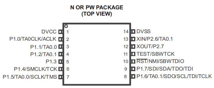
    looks like you will need to sit down with the documentation a little bit! Have a look at the pinout below:


    The device has 14-pin in total. Pin 1 and Pin 14 were the power supply pins, Pin 11 is not available for your application (for debugging only), and Pin 10 ist the Reset or NMI (non maskable interrupt) input (also used for debugging). This will give you a total of 10 availabe I/O.

    For your application you will need at least one input to the ADC (ADC10 means it has a resolution of 10bits) to measure your battery voltage resulting in 9 pins left for the LEDs. If you use the method described in the appnote you will only need 6 I/Os for driving 12 LEDs (instead of 12 when each one is connected individually).

    Rgds
    aBUGSworstnightmare

    P.S. Well, I can help you out with some code for this! No problem! As long as you can help me out with some money in exchange *lol*. Hey Amit, doing this simple app is an easy task! Don't get to confused! Take the Launchpad (when it arrives; waiting for mine for months :-( ) and try the example codes (blinking LED, dealing with ADC). Then go ahead and try the code from the appnote which deals with the LEDs. The appnote also covers the ADC topic! The sensor which they used gives them two voltages (x and y coordinate) which they sample. When this is done they light up the LED for signalizing.

  • aBUGSworstnightmare said:
    If you use the method described in the appnote you will only need 6 I/Os for driving 12 LEDs

    Actually you only need 3 pins for any number of LEDs, but that requires a bit more external hardware. I had to go this way when my ATMega128 was running out of port pins.

    Just attach a shift register to these three pins. One for clock, one for data and one for strobe. Set data to each LEDs state, trigger the clock, and once all 8/16/24 etc data bits are out, trigger the strobe pin. It can even be done using the SPI (if not required otherwise) for clock and data. The only drawback is that you'll need to keep a copy of the LED states as you have to write all LEDs together and cannot alter individual bits by just accessing the port. The HC4094 serves well for this purpose and also acts as current-limiter for the LEDs (you don't need the series resistors)

    The multiplex method described in the mentioned appnote has some serious drawbacks. It does not allow any combination of LEDs. Only up to three can be on at the same time and not any combination of three. To make all LEDs lit, or any other combination, you'll have to constantly switch the output pins with high frequency. 120Hz minimum (better 300) for a non-flickering display. And then only ~1/6 of maximum brightness is available. Not desireable.

**Attention** This is a public forum