This thread has been locked.

If you have a related question, please click the "Ask a related question" button in the top right corner. The newly created question will be automatically linked to this question.

Energy Meter shunt resistor connections problem...

Other Parts Discussed in Thread: MSP430FE427, MSP430F6736

Hi

İ have energy meter board (msp430fe427).

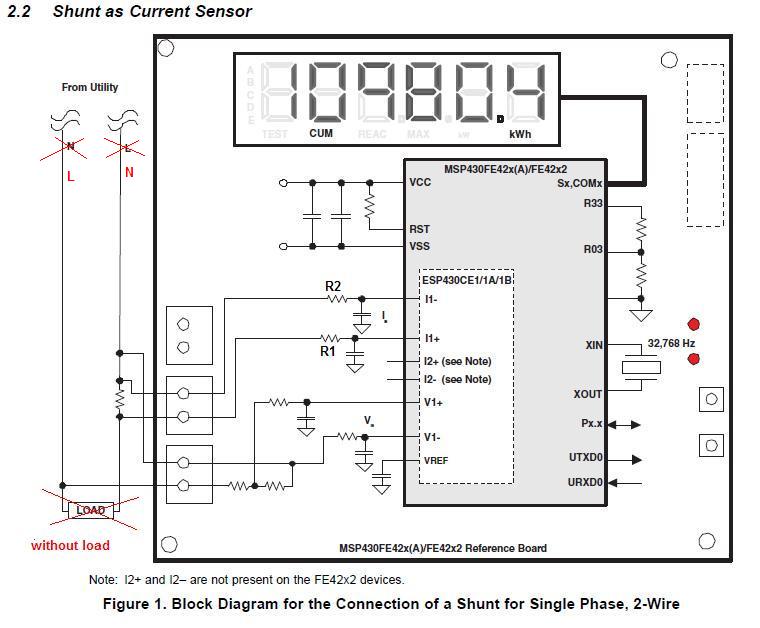
i am using shunt resistor. i did shunt resistor connection according slaa203c doc. page 4. But there is something wrong. whenever i connected the AC line. R1 and R2 resistor is burned. (picture ENERGY-METER-1).

Then i realiazed the document(slaa203c ) shows wrong connections of  the Load and Neutral side.

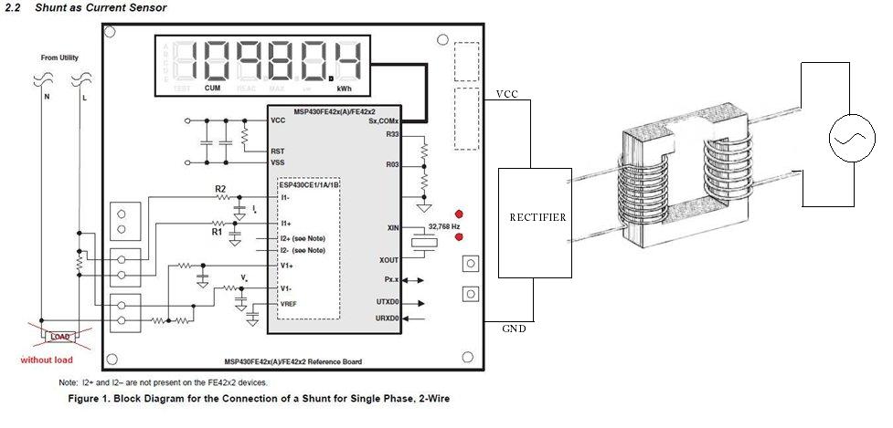
i changed it. (picture ENERGY-METER-2) 

Everything is fine. i can measure without load and with load.

But i think energy meter circuit must be independent  the Load and Neutral.

This card will be a product. users can connect wrong  the Load and Neutral. it must not damage whenever connect. it must measure both connection.

is there any suggestion to succes this.?


ENERGY-METER-1


ENERGY-METER-2

thanks...

  • It's not the L/N side that is causing the problem. It is the fact that your supply voltage is grounded. So GND (and therefore the base level of the AC side) is tied to N. And the inputs are on the live side.

    For the voltage sensor, there is a voltage divider, as the voltage is expected to be high. But on the shunt, the differential voltage is very low, so no divider is there. If you're on the live side with the shunt (and as you said, the customers may not know if it is for a power socket, or simply connect it wrong), then the absolute voltage will be high too, burnign R1 and R2 and (if R1 and R2 resist too long) burn the whole MSP too.

    To make a shunt measurement work, the supply votage must be >=100% isolated from the line. You may not use a switching supply. best would be a battery, second best is a transformer. The plain old type. Which is inefficient, but does a 100% isolation. It allows teh low-voltage side to 'swing' with the sensor inputs if necessary.

    Keep in mind that the whole device counts as a non-isolated device (despite of the necessity of an isolated power supply) and every part of it may have line level relative to ground. Also don't forget that oscilloscopes and interfaces (USB, serial etc.) are grounded too and must not be used. This also applies to the JTAG/FET. Disconnect it before applying the device. (sorry, this means that no debugging is possible, unless you have and opto-isolated connection)

  • Hi Jens-Michael Gross

    i am using 12V adapter to supply MSP board. Adapter has transformer and rectifier. So the  supply votage is isolated from line. But while i was appliying L/N, serial device was connected PC. and also Jtag. this may be cause.

    is this true picture to meter?


    according this connection,(at 220V AC line) on I1+ and I1- reading voltage is around 220 * sqrt(2). so shunt resistor mustnt connect live side. this is big problem. 

    -----------------------------------------------------------------------------------------------------------------------------------------------------------------------------------------------------------------------------------------

    There is a question more i confused.

    in slaa203c, page 26. "power supply"

    is this circuit isolated from the line? 


  • omeraygor said:
    i am using 12V adapter to supply MSP board. Adapter has transformer and rectifier. So the  supply votage is isolated from line. But while i was appliying L/N, serial device was connected PC. and also Jtag. this may be cause.

    Indeed. If the device is connected to PC, its GND potential is connected with earth/N. This means, the shunt inputs have 200V compared to device GND. That will definitely burn the resistors and/or the MSP and/or the JTAG interface and/or the PCs serial port.
    I had to learn this the hard way too, I once burned a device which used a cheap capacitor supply when I connected it to an oscilloscope. Luckily I didn't burn the Oszi too. Now I use a separating transfoerm for all devices I test, the devices power side is isolated from normal power network. As long as the measured current comes from the isolated side too, I can use Oszi and JTAG as I like.

    omeraygor said:
    according this connection,(at 220V AC line) on I1+ and I1- reading voltage is around 220 * sqrt(2). so shunt resistor mustnt connect live side. this is big problem. 

    No, No. If the GND of the device has no connection to N/earth or any other external voltage that is referenced to N, then the inputs have NO voltage potential at all. Only a voltage difference between them. The problem are the two lines directly connected to L and N, but there is a large voltage divider between them. So only the input currents to the MSp inputs define an average potential between the inputs and device GND. This is still in the range of VCC. If it isn't, the input currents raise a bit and then it is again. It is called 'virtual ground',  Only if you make a real ground by somehow connecting it, it will be a problem and full 220V apply.

    omeraygor said:
    is this circuit isolated from the line? 

    No, it isn't. The GND is directly connected (only through an inductor) to P1-, which makes the virtual ground a real ground. It can only be used when the polarity of the measurement inputs is matched to N.

    You'll need to duplicate the 170nF/280V capacitor to the 'return' line too. Without it, it acts similar to a transformer, where one side of the output is wired to one of the input sides. Which still works as a tranfoermer, but isn't isolated anymore.

    Inthis supply type, teh combination of capacitor and resistor acts as a low-pass filter that dampens the input signal to a low voltage level. The output current consumption influences this low-pass too, so the choice of capacitor and resistor has to match the reauired output voltage and current consumption. If the current consumption changes, the output voltage changes too (hence the Z-Diode , which will swallow excess current and keep the voltage down.
    It is a very cheap but very inefficient type of power supply. And normally not isolating. (I don't know how the second capacitor influences the output too, but since these capacitors are usually big  - they have to be X2 type (a self-healing, failsafe construction) and higher currents require even larger ones - and expensive, and a second one increases not only costs but also size and energy loss, so a transformer might be the better choice again)


  • hi jens.

    First of all thanks for help.

    The resistors, caps and msp is burned on my card. i am lucky not burned Pc serial interface and Jtag programmer.

    Now i am changing it. But this is very hard to change msp, new one. 

    i understand you clearly now.

    i have to use Transformer or battery to seperate  Line and my card. 

    i decided using battery for now. then i will use transformer later. as result, high-side current measurement and low side current measurement will not problem for me.  According tihs connection, customers dont need to know L side and N side.

    as you said i tested simulationsly. (attached file.) 

    when Sw1 is closed, the voltage is rising about 220V.

    6011.e-meter-2.PDF

    __________________________________________________

    On slaa203c document, page 24. it says 


    Jumper to connect negative input to GND

    (not assembled)

    the Jumpers J1 and J2, are they being assambled on board?


  • omeraygor said:
    But this is very hard to change msp

    Well, I replaced a few of the 64 pin TQFP types. It's no fun, but possible. Just carefully cut the pins with a cyrpet knife, then you can wipe them off with the soldering iron. Soldering a new one on the board, however, requires some practice. SO unless the MSP on the board has a BGA socket or such (I don't really know), replacing it is possible.

    omeraygor said:
    i have to use Transformer or battery to seperate  Line and my card.

    Well, the capacitor power supply as shown in the appnote can be used, even without the second capacitor. As long as it is hardwired to the proper L/N input terminals. The devastating voltage only appears if the supply lines and the measurement input lines are twisted. If your device is powered by the measured voltage (maybe with a large storage capacitor to power it if the device is removed from the line, all is well. Still no JTAG or serial allowed, of course.

    I looked into your simulation and I think you were placing some routes incorrectly and left out some possibly interresting points, but the result would be the same anyway.

    One more thing that can go wrong: if you use a shunt and you short-circuit the load, then 220V appear across the shunt before the fuse blows (or the shunt breaks, which would still apply 220V across the shunt inputs but would prevent the fuse from being blown). This will destroy the device.
    Even if it isn't a direct short-circuit, it may still temporarily raise the voltage across the shunt to more than the MSP wil bear.

    This is why I prefer a current transformer. Shorting the load will drive the transformer into saturation (provided it was properly selected) and keep the output voltage low.
    In our own application (different setup, using an ADE chip for the measurement and an MSP for the processing, with an isolated data line between the two), we use a current transformer that produces 66mA output @400A primary current. (the other type we use produces 33mA@100A). With a 7.5Ohm resistor parallel to the current inputs, this results in a +-500mVp input signal and < 100mW power consumption including losses (on 92kW load). The transformer core goes into saturation at around 600A, so we won't see any voltage greater than 750mV on out input pins (as long as the 7.5Ohm resistor doesn't burn - not likely at 75mW). For these currents, a shunt is of course impossible at any rate. Even a 0.00006Ohm shunt would glow with 10W here. But even at 10A, the 0.068Ohm shunt will consume 6.8W and produce this much heat.

    omeraygor said:
    the Jumpers J1 and J2, are they being assambled on board?

    I don't know, I don't have have the board.

    I think, these jumper can be used to pin the negative output of a current transformer to GND. Then of course no direct voltag emay be applied to the terminal. SInce the current transfoermers output is isolated and has no petential, it will be given one with these jumpers. Also, if using a transfoerm, it needs a burden resistor (these are also marked as not assembled.
    A current transformer tries (with the limit of its magnetic cores capacity and inner wiring resistance) to output a current that matches the primary current by a certain factor.

    This means, if left open (no burden resistor), it would try to raise the output voltage until the right current flows. Bigger transformers easily build a lightning arc.
    When working for AEG, I tested 1000A:1A current transformers. When I failed to tighten the sensor cables properly, they buzzed a lot (and smelled :) )
    In opposition to a normal voltage transformer, where the voltage will drop with the burden, the voltage over a current burden is constant as long as the total power does not exceed the cores capacity. Even the resistance of the cable doesn't change it. It is just treated as another part of the burden and gets its own share of the output power. The voltage over the burden resistor stays constant. Unlike a shunt, where every additional resistor forms a voltage divider and influences precision.

    The main advantage of a shunt (along with the lower price, at least for low-precision ones) is that there is no phase difference. Output voltage follows current without delay. Transforemers are always a bit behind (3 or 4 degrees normally), which must be compensated by the software). Also, shunts can measure DC currents too, where a passive current transforemer only measures AC (for DC, active current sensors with hall effect are required). But then, on DC applications you usually have no problems with the electric potential :)

    The true challenge of an engineer is not to design a device for normal usage, but to design it so it will survive the unnormal usage. :)
    (This should be true for software programmers too, but this isn't taught at university. As I had to learn once more today.)

  •  

    i changed MSP430 in advence too. :) it has been burned before.

    Jens-Michael Gross said:
    One more thing that can go wrong: if you use a shunt and you short-circuit the load, then 220V appear across the shunt before the fuse blows (or the shunt breaks, which would still apply 220V across the shunt inputs but would prevent the fuse from being blown). This will destroy the device.
    Even if it isn't a direct short-circuit, it may still temporarily raise the voltage across the shunt to more than the MSP wil bear.

    My circuit has SMBJ5.0A. it protects to any voltoge overload.  i think SMBJ5.0A and fuse protect energy meter circuit. 

    http://www.datasheetcatalog.org/datasheet/stmicroelectronics/5616.pdf


    DESCRIPTION

    The SMBJ series are TRANSILTM diodes designed specifically for protecting sensitive equipment against transient overvoltages. Transil diodes provide high overvoltage protection by clamping action. Their instantaneous response to transient overvoltages makes them particularly suited to protect voltage sensitive devices such as MOS Technology and low voltage supplied IC’s.

    in addition, i will try the current transformer later. but for now the sensor using is shunt resistor. i want to see both of them and learn.

    i know 0.068ohm shunt resistor is big for  10 A. But i can not find an other shunt resistor. there was not time to search. Basically, measuring the current with 0.068 ohm is same the other shunt values. only there is one thing i have to consider is Max Ampere and Power over the shunt. 

    Jens-Michael Gross said:
    The true challenge of an engineer is not to design a device for normal usage, but to design it so it will survive the unnormal usage. :)

    this is very nice. and %100 correnct.

    There is my rule too.:)

    With %100 knowledge, at least %80 success. 


  • I know these transil diodes.

    I used one myself for the first versions of our switching power supplay. It had an unregulated secondary output which was ising with the load on the primary output. The transil generated a load that limited the output voltage to <16V during the peaks of the switching process. Worked quite well, but when we raised the primary power output (5V 1A), it got really hot :)
    The current versions uses a step-up regulator to generate regulated 12V from the primary output (now 5V 2A) and only as much as needed. More expensive, but way higher efficiency.

    The shunt should match the application. As long as you stay in the 1A range, things are fine. Our laser power supplay has to regulate a pulsed current of up to 30A, there this shunt would have required its own cooling tower.
    We found really good shunts. Series ISA-PLAN precision resistors,  PBV type. Available from 0.5 to 500 mOhm. 1% tolerance and 4-wire (so you don't measure the voltage across the terminal resistance). Takes 3W uncolled and 10W cooled. And the cost is down to ~2 Euro for the 10mOhm type we use.

    Unfortunately I cannot tell where to get it outside Germany. Manufacturer is Isabellenhuette (www.isabellenhuette.de/en/products). You can try www.distrelec.com and search for PBV. Same for www.buerklin.com. Both offer it, bu tI don't know whether for your country.

    ��mer ayg��r said:
    With %100 knowledge, at least %80 success. 


    I can do better: coin tossing - with 0% knowledge 50% success :)
    (with 100% knowledge, perhaps 51%?)

  •  

     this transil diodes can protect my circuit as soon as the fuse is broken.  

    i am from Turkey. There are the companies pruducing the shunt resistor  in here. i have contacted with them.

    The burned msp430 is changed. and tried it. it is working normally. and i supply it by battery 9V.

    it works independent  both side of L/N, i tried. the result is OK.

    Now, İ am looking for isolated voltage regulator circuit without using transformer and using 220V L/N line.

    is there any suggest by you?


  • omeraygor said:
     this transil diodes can protect my circuit as soon as the fuse is broken.  

    Yep, it should swallow the transient between the load shortcutting and the fuse breaking (once the fuse is broken, there is no more current and therefore no voltage over the shunt). A VDR could do as well (and is probably cheaper), but it isn't as precise and may influence the shunt reading even in normal operating range.

    omeraygor said:
    Now, İ am looking for isolated voltage regulator circuit without using transformer and using 220V L/N line.

    You don't need to have an isolated supply, as long as the supply is directly fed by the same terminals the measurement L and N are connected to. So if L and N are switched, the supply is switched too and all is well. The capacitor supply will be fine. If should be, however, placed on the same PCB, so nobody can twist the connections.

    There are, however, several supply modules available which take 230V and output 3.3, 5 or 12V. It is a question of price, size and required load. These modules, however, usually provide much more current than you'll need.

  • hi.

    yes, it is about price. it is limited for this project. This must be low coast. 

    i am thinking using capacitor supply. 

    i will use capacitor supply and shunt resistor.

     7723.00954A.pdf

    Thanks...


  • hi Jens.

    how are you.

    i fixed my problem about supply.

    Now. i am confused about calibration. in slaa203 page 22. step 2 

    Attach the meter to an I/V generator adjusted to the calibration values defined in the Settings Excel file

    (e.g., 240 V, 10 A, 60° phase shift).

    now. i dont have i/V generator. and i googled it. and culdnt found anything. what is this equipment. and is there any simple way to calibrate meter?


    Thanks...

  • omeraygor said:
    how are you.

    I'm still here :) and I'm fine, thanks (nothing but the usual)

    omeraygor said:
    what is this equipment

    This refers to a programmable/adjustable AC voltage source and current sink. It simulates line and load. Can be one monolithic device or two independent ones.

    You don't necessarily need such an expensive equipment.

    All you need to do is to have a voltage source and a current sink that generate fairly constant values. e.g. an adjustable transformator (220V in, 0-250V out, for more than one calibration pioint), simplest case just the AC line (then only 1-point calibration for th evoltage input). And a load that is partly capacitive or inductive, e.g. a synchron motor, so you have an angle between V and I.
    And last you'll need a good, calibrated multimeter with power reading, to measure all three.

    Just write down the multimieter readings and the MSP results synchroneously for one voltage/current and then again for a different voltage/current, and you can calculate the required calibration values for offset and gain.

    Using an I/V generator, however, allows to automate the process, as the code in the MSP then knows what to expect and what really comes in. Way more programming, but almost no work in the production.

    I built a small budged version with an MSP and a power and a high-Voltage OPAMP. It just generates sine waves for the voltage input and at the same times simulates the (small) current of the current transformers. This allows the MSP to automatically gather all calibration information. It's more difficult for the current shunt version, as there the current inputs are not decoupled from the line, and you'll have to drive the large current with, well no OpAmp drives several amperes, or need to measure the shunt toleranceput it into the generator, hook-off the shunt from the current input, and then inject the simulated shunt voltage  into the circuit.

  • Hello Jens-Michael Gross,

    I was going through this post and I must admit; I am a bit confused.

    Following is a list of questions along with reference images.
    You may find them naive but I would be obliged to have them answered.

    Measurement specific:

    Reference:
    SLAA517A
    Single-phase EM with MSP430F6736
    Page # 6:
    image: MSP43F6736_1PEM_Curr_AFE_#6.jpeg

    01. How does this circuit behave?

    02. What is the significance of pairs D1-D2, D4-D5, D6-D7 & D9-D10?

    03. AVCC & AGND:
    Are they generated from the SAME single phase supply?

    04. Can this circuit be tested with external power supply set to desired AVCC & AGND?

    05. Which channel out of the shown two, be used for Shunt measured current?

    06. Why do the channels differ in R13-R15 implementation?

    07. Is there any major difference in this circuit and a usual amplifier feeder circuit feeding two difference signals; apart from anti-aliasing circuitry?

    08. What are the "signals" to be seen on the two feeding points (IN+, IN- and IL+/IL-)?

    SHUNT specific:


    Why Shunts used in EM applications have three terminals?
    How would be the connections for a shunt in line (with reference to the said image, black, white & red wire terminals)?

    Best regards,
    --Utpal 

  • 01. How does this circuit behave?

    It provides (a little) protection against over or under voltage, and it filters out high frequency components of the differential analog signals.

    02. What is the significance of pairs D1-D2, D4-D5, D6-D7 & D9-D10?

    D1, D4, D6, and D9 try to make sure that the analog signals stay below AVCC. While D2, D5, D7, and D10 try to make sure that the analog signals stay above AGND.

    03. AVCC & AGND:
    Are they generated from the SAME single phase supply?

    These are the power supply and ground of all the on-chip analog circuits. They must be connected to a power source off the chip; usually but not necessarily, the same as the source for DVCC and DGND.

    04. Can this circuit be tested with external power supply set to desired AVCC & AGND?

    Yes, but it must be between 1.8V and 3.6V, and DVCC & DGND must be at the same voltage.

    05. Which channel out of the shown two, be used for Shunt measured current?

    LSP3 & LSP4 can be connected to the Shunt resistor.

    06. Why do the channels differ in R13-R15 implementation?

    LSP1 & LSP2 can be connected to a current sensing transformer which is isolated from the rest of the world, thus this circuit provide a ground through R13-R15 so that it is not floating.

    07. Is there any major difference in this circuit and a usual amplifier feeder circuit feeding two difference signals; apart from anti-aliasing circuitry?

    No.

    08. What are the "signals" to be seen on the two feeding points (IN+, IN- and IL+/IL-)?

    They are the protected and filtered differential analog signals connected to the ADC of the MSP430 chip.

    SHUNT specific:

    Why Shunts used in EM applications have three terminals?
    How would be the connections for a shunt in line (with reference to the said image, black, white & red wire terminals)?

    Black, white, & red are to be connected to AGND, LSP4 & LSP3 respectively.

  • Many thanks Mr. OCY.

    I should be implementing your suggestions immediately and posting the results here soon.

    Regards,
    --Utpal 

  • old_cow_yellow said:
    03. AVCC & AGND:
    Are they generated from the SAME single phase supply?
    These are the power supply and ground of all the on-chip analog circuits. They must be connected to a power source off the chip; usually but not necessarily, the same as the source for DVCC and DGND.

    For best performance, it is recommended to put at least a low-pass filter (10 to 200 Ohms series resistor and 10µF Tantalum/100nF ceramic combo) between DVcc and AVcc. Also, AVss should be reoputed separately to GDN point of the supply, so currents on the digital GND won't create a ripplign analog GND reference.

    old_cow_yellow said:
    04. Can this circuit be tested with external power supply set to desired AVCC & AGND?
    Yes, but it must be between 1.8V and 3.6V, and DVCC & DGND must be at the same voltage.

    Well, almost the same. A variation of up to 0.2V is allowed (clamp diodes between DVcc/ss and AVcc/ss). This is enough to have a filtered, ripple-free version of DVcc on AVcc.

    old_cow_yellow said:
    Why Shunts used in EM applications have three terminals?
    How would be the connections for a shunt in line (with reference to the said image, black, white & red wire terminals)?
    Black, white, & red are to be connected to AGND, LSP4 & LSP3 respectively.


    Well, usually there are four terminals. The shunt you posted actually has five. The mounting holes are the terminals for the current path, while there are separate terminals for the voltage measurement.
    The reason is that the voltage teminals attach to the current path with the specified shunt resistance between them. If you'd measure at the mount holes instead, you had the additional contact resistance in addition to the shunt resistance, and would measure significantly more voltage - with an even changing factor.
    I guess, the 5th terminal allows for a current return and fixes one side of the shunt to (or near, which makes no difference as differential voltage over the shunt is measured) the circuit GND level, without causing an additional voltage drop on the voltage sense wires.

**Attention** This is a public forum