This thread has been locked.

If you have a related question, please click the "Ask a related question" button in the top right corner. The newly created question will be automatically linked to this question.

MSP430FR2633: In REGISTER I2C mode, the MSP430FR2633 do not send the acknowledgment.

Part Number: MSP430FR2633
Other Parts Discussed in Thread: MSP430F149, , MSP430FR2311

Hi,

I am using the MSP430FR2633 as the Slave device in REGISTER I2C mode. My host or master  is MSP430F149 micro controller. This host do not have the seperate I2C module so we use the bit banging technique to create I2C mode. 

According to the following example by TI, we need to send the [Slave address with write] + [COMMAND ID] + [SENSOR ID].

So my default write will be [0x0A] + [0x00] + [0x00].

But I could not receive the acknowledgment after I sent the [Slave address with write] which is [0x0A]. 

Example:
Sensor Packet Example: Getting Dominant Element and Using the Checksum

In this example, we will use the same sensor packet request as in the original example above, with two differences: we are going to extract the dominant element and we are going to read back the checksum as well to validate the transaction. To read the checksum, we just read an additional two bytes after the 6 bytes of the packet (8 bytes total). The checksum is 16 bits, lower byte first, and is calculated from byte 0 to byte 5 (the entire packet excluding the checksum itself). The data capture shown here was taken while a touch was present on element 2. This is to shown what data looks like when an actual touch is present.

void loop(void)
{
    static uint8_t tx[16];
    static uint8_t rx[16];

    if (capture==true)
    {
        capture = false;

        tx[0] = 0x00;
        tx[1] = 0x00;
        I2CMaster_writeBuffer(0x0A, &tx[0], 2);
        I2CMaster_readBuffer(0x0A, &rx[0], 8);

        if ((rx[5] & BIT0) && (rx[2] == 0x02))
        {
            // Element 2 is touched
            P1OUT |= BIT0;
        }
        else
        {
            // Element 2 is not touched
            P1OUT &= ~BIT0;
        }
    }
}
  • Hi Parth,

    I believe the slave address you send out will be shifted to the right by the I2C module so it can set/clr bit0 - R/W bit. Try 0x06 instead of 0x0A.
  • Hi Dennis,

    I tried 0x06 but still the issue is I do not get ACK from MSP430FR2633 after I sent the Slave Address with R/W bit either clear or set.
    If my slave address is 0x0A then my Read with Save will be 0x0B and write will be 0x0A.
    In order to write to the MSP430FR2633, I sent [0x0A]+[0x00]+[0x00].
    Also, When I use debugger for MSP430FR2633, and put the breakpoint on the #pragma vector=I2CSLAVE__EUSCI_VECTOR
    __interrupt void I2CSlave_ISR(void), I never hit the breakpoint even if I want to write or read.
  • Hi Parth,

    My bad: 0x0A >> 1 = 0x05, try 0x05.

    Do you also have an oscilloscope or logic probe to see what the SDA and SCL lines are doing?
  •  Hi,

    I figured out that one and I tried with 0x05. That did not work and also i try the shifting 1 bit to the left and also that is not working.

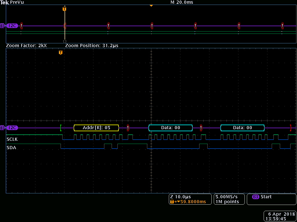
    I am sending you this screen shot of capturing sequence.

  • Parth,

    You indicated you are bit banging the MASTER I2C.  It doesn't appear you are shifting the slave address 0x0A << 1 and setting bit 8 = 0 (write operation).

    See example master write to MSP430FR2633 slave @ 0x0A below.

  •  Hi Dennis,

    I actually figured that out by sending the address 0x14 for the write operation so even if i shift to the left 1 bit, i will still send the address 0x0A with R/W bit = 0. Now with the write operation i can receive ackwnodlege back after the slave receive the proper address (0x0A).

    Now when I tried to read with slave address 0x0A, because of the one bit left shift, i need to send the address as 0x15. Am i right ?? please correct me !!!

    Basically i want to read the Sensor parameter packet every 30 millisecond and from that i will determine which key  is touched in my Keypad sensor group.

    according to the following program (which was written by TI), i need to write with Sensor ID and Command ID first and then I will be able to read the Sensor Parameter Packet from MSP430FR2633 (slave). Please correct me if i am wrong.

  • Yes, you are correct. And yes, you will send 0x15 for a read operation. Good Job!!!

    Let me know how this works for you.
  • Hi Parth,

    I'm going to close this thread since it has been a few days since your last response and I'm assuming you have resolved your issue.
    If this is not the case and you need additional help, you can re-open this same thread.
  • Hi Dennis,

    Sorry for not replying back quick enough!!

    I was away from work and I was trying to read the Senesor PArameter from MSP430FR2633 as we discussed earlier.

    Now I am able to 'write' in REGISTER I2C mode but when I tried to read with BSWP board, I am not able to get the 'Sensor Packet' properly.

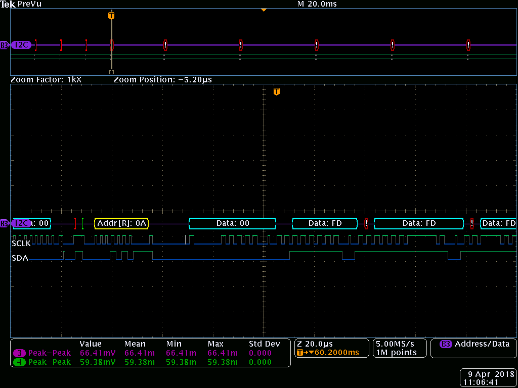
    I am attaching the screenshot of the 'Read' command for the Sensor Packet. Please guide me.

    As per TI example, to read the Sesonr PAcket from the Slave, We need to write to Slave first, so I am sending [0x14]+[0x00]+[0x00] for demo- BSWP board 8 button group.

    No when I am sending [0x15] to read the sensor parameter back, I can not read the data back in proper format. As you knew already, we are not using dedicated I2C mode on Master, but we use bit banging technique.

    Please advice.... 

  • Hi Parth,

    My first thought is if you have the MSP430FR2633 programmed and running in the REGISTERI2C mode, then it should work.

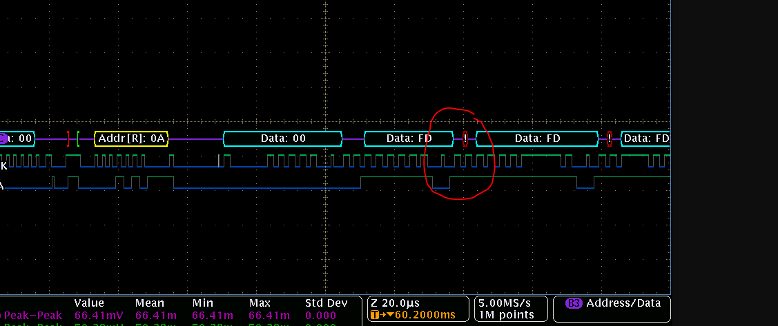
    I did notice on your data capture that it appears the host is generating a NACK after the first byte, based on the SDA = 1 on the 9th clock bit.

    You might want to check this.  Also, try putting a little delay in between when you read each byte.  This will spread out the data capture and make it easier to see the clocks for each data and ACK/STOP etc.

    To make sure the BSWP code is working, I setup my MSP430FR2633 as yours and have an MSP430FR2311 launchpad acting as the host.

    As you can see the host performs the write with 0x00,0x00 as data.  The host then reads 6 bytes from the MSP430FR2633 while I am touching the sensors.

  • Hi Dennis,

    I have different question.

    Master (MSP430F149) is continuously asking Slave (MSP430FR2633) for the Sensor Packet every 100 millisecond.

    Now if i press one button for the BSWP panel, i can get the proper element number in the Sensor Packet but when I released the touch, the new Sensor packet do not delete the information of last touched element.

    Example: if i pressed button 5 of the BSWP keypad, I received the dominant element will be 4 ( 0 is the first element), but when i released the touch from the button 5 and asked for the Sensor Packet again, the new sensor packet still has the previous dominant element button 4. 

    Is there any other way to read which button is being touched and if they released the touch or not ? 

  • Hi Parth,

    Check byte 3 of the sensor packet (described here).  Bit 0 is the sensor's touch flag.  

    You should check the status of this bit first, then check what the dominant button is.

**Attention** This is a public forum