This thread has been locked.

If you have a related question, please click the "Ask a related question" button in the top right corner. The newly created question will be automatically linked to this question.

MSP432P401R: Using Launchpad XDS110 to program external MSP432P401R

Part Number: MSP432P401R

Hello,

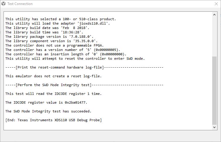
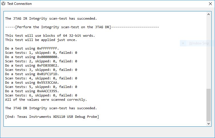
I have an external MSP432P401R on a PCB that I'm trying to program with the Launchpad XDS110 and I'm getting this error in CCS:

I followed all guidelines in the Launchpad manual section 2.3.4 Using the XDS110-ET Debug Probe With a Different Target

ALL jumpers were removed from J101. I have 5 wires going from the Launchpad XDS110 to my processor: TDI, TDO, TMS, TCK and RST. 

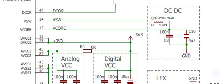
I'm also supplying 3.3V and GND from my PCB, not from the Launchpad. I've confirmed that I have 3.3V at AVCC1, AVCC2, DVCC1 and DVCC2. I also confirmed that the proper pins are grounded: AVSS1, AVSS2, AVSS3, DVSS1, DVSS2 and DVSS3. I've triple checked that the pins are correct on my PCB for the programming circuit but I'll show them here:

I connected the 5 wires TDI, TDO, TCK, TMS and RST from the MSP432 to the pins listed above on the XDS110 J101 pins on the launchpad. 

If it's worth noting, when I first tried to program to MSP432 it seemed to connect properly but when I hit PLAY to run the debugger it gave me error -1170 (I didn't get a screenshot). Every other time after that initial, I've gotten the error I listed initially in this post. 

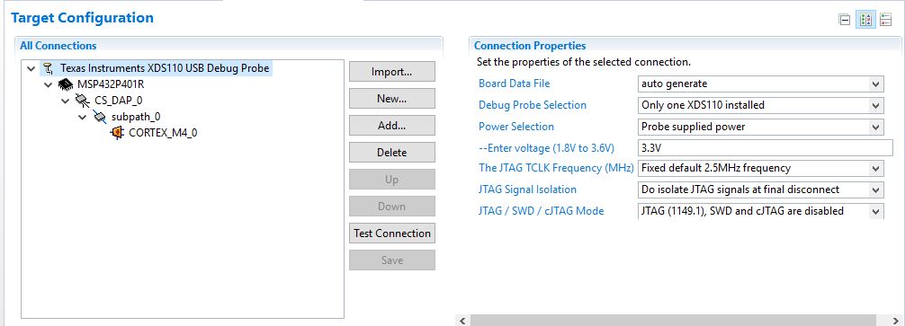
Any help is appreciated, is there anything you notice in my setup or any configuration change I may need to implement in CCS? 

I'm able to run the debugger with the onboard MSP432 on the launchpad just fine. 

I also checked to see if I had any updates in CCS but there weren't any. Here's my version of CCS:

Thank you. 

  • Jacob,

     I'd first refer you to this reference (in step 2) to see if the XDS110 is in runtime mode. Usually just unplugging/replugging the launchpad will reset the XDS110 to runtime mode. If when running the xdsdfu -e command mentioned in the reference indicates it is in DFU (firmware update) mode, then follow the instructions to reset the debug probe back to runtime mode.

    Another user reported that a reboot fixed the problem with Error -1170. - see this post for more details, but here's the summary

    - part of the problem discovered in that post was the the firmware had corrupted the ability of the Cortex-M core to be accessed.

    - The device could still be programmed by following this procedure. 

    1. Instead of just going for 'Debug', build the project, then launch the target configuration
    2. Connect to the target
    3. Do a 'CPU Reset', and wait for the CPU to restart and pause during boot
    4. While paused, do a 'Load Program'

    Other References that may help.

    http://processors.wiki.ti.com/index.php/Debugging_JTAG_Connectivity_Problems#Cannot_access_the_DAP 

    I think this procedure, or other info from the Wiki page, will fix your issue.

    Regards,

     Bob L.

  • To help further debug, I tried powering my target PCB from the launchpad -- I put a jumper on the JP102 pins for "Enable XDS110 Power out" with the following settings in Target Configuration:

    I tried "SWD Mode - Target is TDO pin" as shown above with the following Test Connection results:

    I also tried to switch to "JTAG - SWD and cJTAG disabled" as shown below:

    And the following JTAG test connection results:

    Still having a connection issue with error -261 invalid response from XDS110.

    Also one more thing I tried. I used the XDS110 from one MSP432 launchpad to program a second launchpad and that worked just fine. This leads me to believe it could be a hardware issue, I've gone over the Launchpad schematic thoroughly and can't seem to pinpoint a specific error. I also replaced the MSP432 on my PCB to no avail. 

  • Bob,

    Thanks for the reply.

    "I'd first refer you to this reference (in step 2) to see if the XDS110 is in runtime mode. Usually just unplugging/replugging the launchpad will reset the XDS110 to runtime mode. If when running the xdsdfu -e command mentioned in the reference indicates it is in DFU (firmware update) mode, then follow the instructions to reset the debug probe back to runtime mode."

    - how do I run the xdsdfu-e command to check the mode of the XDS110? Is there a document available to does a step by step procedure on that?

    I tried to do a Reset by just building the project and then launching the configuration. When I selected "show all cores" shown below:

    When I right clicked on CS_DAP_0 and selected "connect to target" I again got this error:

  • The link (where it says "this reference") points to a document that explains where to find the xdsdfu command.

    To skip that step, you can just go to C:\ti\ccsv7\ccs_base\common\uscif\xds110  and read the ReadMe.txt file for instructions.

    I'll have a look at the additional information you sent to see if it helps on debug.

    -Bob

  • Bob,

    After further debugging, I used a bare PCB with a new msp432, filter caps, 47k reset pullup resistor and programming jumper. Using SWD mode with SWDIO/SWCLK/RST and GND connected from the launchpad to the external msp432 on the PCB I was able to successfully program the blink LED example code from resource explorer.

    I programmed it and did a power cycle 5 times with no problems. Using the same configuration with the same msp432 I tried to load my code on and received the error -261 from above. It seems to be a code issue.

    I have a few questions:
    1. Some ports on the MSP432 are not "full ports". I am writing P10OUT as a control port for a LCD Display (This code worked on MSP432 Launchpad). The two highest bits for port 10 (10.7 and 10.6) are not on the MSP432 Datasheet. Are these used for programming? (Specifically SWDIO and SWCLK?)

    2. Are there any ports or pins that should not be written to on the MSP432 as they are used for programming?

    3. Now that I am unable to connect to the MSP432, is there a way to perform a hardware reset, or is my only option to replace the MSP432?
  • After the msp432 was bricked I then programmed the launchpad with the same code just fine. I'm not too sure why it's not working with my pcb msp432 but works with the launchpad. 

  • I'm almost positive I found the problem to all of this. I'm running the processor at 48MHz and am using

    PCM_setPowerState(PCM_AM_DCDC_VCORE1);

    PCM_setCoreVoltageLevel(PCM_VCORE1);

    Unfortunately on my PCB design I didn't have the DC-DC circuit between VCORE and VSW shown below

    So without this and trying to enable the DCDC converter, I believe it's causing a Power-on Reset from what I've read online. I'm going to add this circuit to my PCB to see if it fixes the problem.

  • Adding the VCORE/VSW DCDC converter circuit above fixed my problem.

    Thanks for the help!

  • Jacob,
    Definitely a problem- that inductor/capacitor circuit MUST be there for the DCDC to work properly, as you discovered.
    -Bob

**Attention** This is a public forum