This thread has been locked.

If you have a related question, please click the "Ask a related question" button in the top right corner. The newly created question will be automatically linked to this question.

CCS/MSP-EXP432P4111: uart loopback 24mhz

Part Number: MSP-EXP432P4111

Tool/software: Code Composer Studio

uart_loopback_24mhz_brclk does not work for me

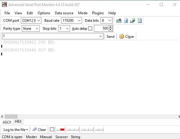
I installed CCS V8 thinking that might solve it yet I do not get it to send or receive data at 115200 

I need a working uart program to communicate with the TI BQ76PL455 chip.

  • Michael,
    This example does not send data to the PC, so you won't be able to observe anything except the presence/absence of the Red LED on P1.0, which will turn ON if there is an error in communication.
    Note that you will also have to short pins 3.2 and 3.3 together for this example to work.

    To see data on a PC terminal emulator, try the uart_pc_echo_12mhz_brclk example .
    Regards,
    Bob L.

  • Thanks for the response Bob,

    Yes shorting 3.2 & 3.3 and removing the short does get the red LED on.

    I purchased the FTDI TTL-232R-3V3 cable and have it now between the 3.2 & 3.3 pins.  With the Baud rate and all set, I should see the 0 or 1 being sent and then I could send the response back, correct?

    However the Red LED never turns on.  I need 115200 comm rate for use with the BQ76PL455 which is why I wanted to work with this program.

    Is there a flaw in my logic using the FTDI cable?

  • Michael,

     As I was trying different ways for this example to fail I notice that if you never put the jumper across P3.2/P3.3, then the example will send data and wait for an interrupt that never comes (since the RX pin doesn't get any data). In this case, the error LED on P1.0 gets initialized LOW and never gets to the  EUSCIA2_IRQHandler where it gets set HIGH if TXData <> RXData.  I've reworked the code a bit with the following changes:

    1. P1.0 is initialized HIGH (so if we never see an interrupt, you'll see that as an error)
    2. P1.0 gets set either Hi/Lo depending on seeing correct data
    3. Added P2.0,P2.1,P2.2 as outputs (connects to the RGB LED) to use an activity light- it will cycle through colors if you are seeing correct data flow through the UART.
    4. Corrected the UART Baud Rate settings to actually deliver 115200 kBaud, per the BaudRate calculator.

    New Example code follows:


    /***************************************************************************
    * MSP432 UART - Loopback with 24MHz DCO BRCLK
    *
    * Description: This demo connects TX to RX of the MSP432 UART
    * The example code shows proper initialization of registers
    * and interrupts to receive and transmit data. If data is incorrect P1.0 LED
    * is turned ON.
    *
    * MCLK = HSMCLK = SMCLK = DCO of 24MHz
    *
    *         MSP432P4111
    *       -----------------
    *      |                 |
    * RST -|     P3.3/UCA2TXD|----|
    *      |                 |    | !! Must short these pins for
    *      |                 |    | the example to work
    *      |     P3.2/UCA2RXD|----|
    *      |                 |
    *      |             P1.0|---> LED (Error signal)
    *      |     P2.0,2,1,2.2|---> RGB LED (Activity light)
    *      |                 |
    *       -----------------
    *****************************************************************************//* DriverLib Includes */

    #include <ti/devices/msp432p4xx/driverlib/driverlib.h>

    /* Standard Includes */
    #include <stdint.h>
    #include <stdbool.h>

    volatile uint8_t TXData = 1;
    volatile uint8_t RXData = 0;
    volatile uint32_t count=0;

    /* UART Configuration Parameter. These are the configuration parameters to
    * make the eUSCI A UART module to operate with a 115200 baud rate. These
    * values were calculated using the online calculator that TI provides
    * at:
    * software-dl.ti.com/.../index.html
    */
    const eUSCI_UART_Config uartConfig =
    {

    EUSCI_A_UART_CLOCKSOURCE_SMCLK, // SMCLK Clock Source
    13,                             // BRDIV = 13
    0,                              // UCxBRF = 0
    0,                              // UCxBRS = 0
    EUSCI_A_UART_NO_PARITY,    // No Parity
    EUSCI_A_UART_MSB_FIRST,    // MSB First
    EUSCI_A_UART_ONE_STOP_BIT, // One stop bit
    EUSCI_A_UART_MODE,         // UART mode
    EUSCI_A_UART_OVERSAMPLING_BAUDRATE_GENERATION // Oversampling

    };

    int main(void)
    {
    /* Halting WDT */
    MAP_WDT_A_holdTimer();

    /* Selecting P3.2 and P3.3 in UART mode and P1.0 as output (LED) */
    MAP_GPIO_setAsPeripheralModuleFunctionInputPin(GPIO_PORT_P3,
    GPIO_PIN2 | GPIO_PIN3, GPIO_PRIMARY_MODULE_FUNCTION);
    MAP_GPIO_setAsOutputPin(GPIO_PORT_P1, GPIO_PIN0);
    MAP_GPIO_setOutputHighOnPin(GPIO_PORT_P1, GPIO_PIN0);
    MAP_GPIO_setAsOutputPin(GPIO_PORT_P2, GPIO_PIN0|GPIO_PIN1|GPIO_PIN2);
    MAP_GPIO_setOutputLowOnPin(GPIO_PORT_P2, GPIO_PIN0|GPIO_PIN1|GPIO_PIN2);

    /* Setting DCO to 24MHz (upping Vcore) */
    MAP_FlashCtl_A_setWaitState(FLASH_A_BANK0, 1);
    MAP_FlashCtl_A_setWaitState(FLASH_A_BANK1, 1);
    MAP_PCM_setCoreVoltageLevel(PCM_VCORE1);
    CS_setDCOCenteredFrequency(CS_DCO_FREQUENCY_24);

    /* Configuring UART Module */
    MAP_UART_initModule(EUSCI_A2_BASE, &uartConfig);

    /* Enable UART module */
    MAP_UART_enableModule(EUSCI_A2_BASE);

    /* Enabling interrupts */
    MAP_UART_enableInterrupt(EUSCI_A2_BASE, EUSCI_A_UART_RECEIVE_INTERRUPT);
    MAP_Interrupt_enableInterrupt(INT_EUSCIA2);
    MAP_Interrupt_enableSleepOnIsrExit();

      while(1){
        MAP_UART_transmitData(EUSCI_A2_BASE, TXData);
        MAP_Interrupt_enableSleepOnIsrExit();
        MAP_PCM_gotoLPM0InterruptSafe();
      }

    }

    /* EUSCI A2 UART ISR */
    void EUSCIA2_IRQHandler(void)
    {
      uint32_t status = MAP_UART_getEnabledInterruptStatus(EUSCI_A2_BASE);

      MAP_UART_clearInterruptFlag(EUSCI_A2_BASE, status);

      if(status & EUSCI_A_UART_RECEIVE_INTERRUPT_FLAG){
        RXData = MAP_UART_receiveData(EUSCI_A2_BASE);
        if(count & 0x1000)MAP_GPIO_toggleOutputOnPin(GPIO_PORT_P2, GPIO_PIN0);
        if(count & 0x2000)MAP_GPIO_toggleOutputOnPin(GPIO_PORT_P2, GPIO_PIN1);
        if(count & 0x4000)MAP_GPIO_toggleOutputOnPin(GPIO_PORT_P2, GPIO_PIN2);

        if(RXData != TXData) {
          MAP_GPIO_setOutputHighOnPin(GPIO_PORT_P1, GPIO_PIN0);
          while(1);
        }
        else{
          MAP_GPIO_setOutputLowOnPin(GPIO_PORT_P1, GPIO_PIN0);
        }
        TXData++;
        count++;
        MAP_Interrupt_disableSleepOnIsrExit();
      }

    }

  • I really like your updated program Bob!

    Having the RGB lights indicate activity is great.

    I do not see anything being received on the FTDI cable which I have set at 115200, 8 N 1

    Does that sound correct?

    Thank you for the updated program.

    Mike

  •  Hi Bob,

    I connected 2 of the FTDI cables together with TX going to RX on each and get good ASCI going both ways.

    Connecting the MSP432 board up I can get 8 0 Hex or see the picture for ASCI

  • Michael,
    I am unclear if this issue is resolved. Were you able to get the communication working? If not, is your serial tool expecting MSB or LSB first?

    Regards,
    Chris
  • Thanks for the follow up Chris,

    I was not able to get it to work.  You can however close this.

    Regards, Mike

**Attention** This is a public forum