This thread has been locked.

If you have a related question, please click the "Ask a related question" button in the top right corner. The newly created question will be automatically linked to this question.

MSP430F5359: Please help me understand how low-power mode interacts with the USCI UARTs

Part Number: MSP430F5359
Other Parts Discussed in Thread: MSP430F2618, MSP430WARE,

SLAU208P (the MSP430x5xx and MSP430x6xx Family User's Guide) makes the following statement:

36.3.14 Using the USCI Module in UART Mode With Low-Power Modes

The USCI module provides automatic clock activation for use with low-power modes. When the USCI
clock source is inactive because the device is in a low-power mode, the USCI module automatically
activates it when needed, regardless of the control-bit settings for the clock source. The clock remains
active until the USCI module returns to its idle condition. After the USCI module returns to the idle
condition, control of the clock source reverts to the settings of its control bits.

Let's suppose I've set up a UART (say, UCA1) as follows:

  • It's clocked from SMCLK
  • SMCLK is driven from MCLK
  • MCLK is driven from the FLL DCO at 8 MHz
  • RXIE for this UART is enabled

Then, suppose I put the microprocessor into low-power mode (say, LPM3) so MCLK and SMCLK are off.

Interpreting Section 36.3.14 freely, I'd assume that a Marking-to-Spacing transition on the Rx Data line coming into the UART would activate the UART and the UART would then request SMCLK (hopefully in time to catch the incoming asynch Start bit or at least the first data bit). Then, I'd further hope that the setting of RXIFG at the end of the character would cause an interrupt that would take the microprocessor out of LPM3 while the USCI_A1_VECTOR interrupt is being processed.

But for me, this doesn't seem to be happening. My UART only receives characters when some other action in my system has already taken the microprocessor out of LPM3.

Am I reading that paragraph too optimistically and hoping for too much automation? Or am I failing to set up some bit that's blocking this bit of automation?

Notes:

  1. TRANSMITTING characters from the UART seems to properly request/enable SMCLK.
  2. I don't see anything in the device Errata that is relevant to this.
  3. Substantially the same code worked without this difficulty on our previous MSP430F2618 design but that's no guarantee that I ported everything correctly/completely.
  • Hi Atlant,
    Have you tried recreating this with example code? Note, you will need to change the LPM mode: dev.ti.com/.../
  • I've run a similar test but will definitely compare your example code to my test code; thanks! I'll report back. (Just a note: With my code blocked from ever entering LPM3, UCA1 is working fine for me. We have a large Integration Test suite that depends upon that and it's running successfully right at this moment.)

    Thanks for reminding me about "Port Mapping" but because I'm using UCA1 (on my '5359), I don't think that applies to me. But are there any other bits that would block UCA1 from being able to request successfully SMCLK?

  • Cameron:

    Okay, I've compared your example code to my operational code and they are substantially similar.

    I've also imported your example code into the __low_level_init() routine of my (IAR) application and run some experiments. The example code was from:

    ./msp430ware_3_80_03_07/examples/devices/MSP430F5xx_6xx/MSP430F565x_MSP430F665x_Code_Examples/C/msp430f665x_uscia0_uart_04.c

    Here's the resulting code I used. (Note: The "Debug UART" referred to in my code is UCA2 and isn't participating in this experiment. Commenting-out that initialization code doesn't change the result.)

       int __low_level_init(void)
       {
          WDTCTL = WDTHoldMode;                                     // Switch from "Watchdog Timer" mode to "Interval Timer" mode and hold the WDT
    
          IO::init();                                               // Init the I/O ring
          SysClocks::init();                                        // Init the clocks, Timer A, and the WDT
          RS232::init();                                            // Get the Debug Port UART operational
    
          
          UCA1CTL1 |= UCSWRST;                      // **Put state machine in reset**
          UCA1CTL1 |= UCSSEL_2;                     // SMCLK
          UCA1BR0   = 4;                            // 8MHz 115200 (see User's Guide)
          UCA1BR1   = 0;                            // 8MHz 115200
          UCA1MCTL  = UCBRS_5 | UCBRF_3 | UCOS16;   // Modln UCBRSx=5, UCBRFx=3, Use over-sampling
          UCA1CTL1 &= ~UCSWRST;                     // **Initialize USCI state machine**
          UCA1IE   |= UCRXIE;                       // Enable USCI_A1 RX interrupt
    
          __bis_SR_register(            GIE);       // Enter LPM0, interrupts enabled
    //    __bis_SR_register(LPM0_bits      );       // Enter LPM0, interrupts enabled
          __bis_SR_register(LPM3_bits      );       // Enter LPM0, interrupts enabled
    
          for ( uint32 i = 0; i < 1000000000; i++ ) // Essentially endlessly...
          {                                         //   :
             DB_TP_XP_OUT_REG |=  DB_TP_XP_BIT;     //   :
             DB_TP_XP_OUT_REG &= ~DB_TP_XP_BIT;     //   :
          }                                         //   :


    It differs from your example UART setup code only in that my MCLK/SMCLK is set to 8MHz, my UART is set to 115,200 bps, and I'm using the UCA1 UART instead of the UCA0 UART. I also have a "main loop" that continuously toggles a debug pin on my module.

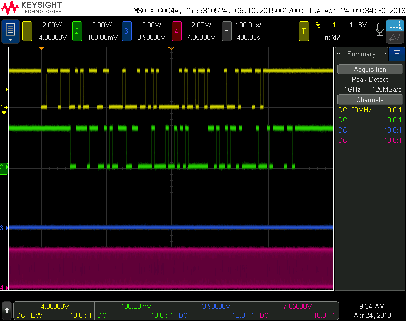
    For all of the 'scope shots below:

    • The Yellow trace is RXD at the UART
    • The Green trace is TXD at the UART
    • The Blue trace is my debug pin
    • The Pink trace is SMCLK

    With both of the "Enter Low Power Mode" lines commented-out, here's the result:

    What you can see is that received data is echoed back as transmitted data (by the ISR). The Blue trace ("Mainline running") has gaps where the UART ISR was active. (It's also got a bigger gap where the WDT ISR was active.) SMCLK was constantly active.

    With the "LPM0" line of my test program active, here's the 'scope trace:

    This is the same except "Mainline" never runs (no surprise here). Because it's just LPM0 and I haven't set SMCLKOFF, SMCLK is always active.

    With the "LPM3" line of my test program active (as shown in the source above), here's the 'scope trace:

    Now, there's never any SMCLK and the received character ISR is never entered so there's no echoing of the received characters.

    THIS is the defect that existed in certain MSP430 processors after the MSP430F2618 that we've been using and I'm afraid that this defect is still present ('though undocumented) in the MSP430F5359 that we're trying to convert to.

    If the hardware actually contains that defect, we'll work around it by double-routing the UART RXData line to a GPIO Input that is set to generate interrupts on a falling edge but I'd rather hear that the hardware is correct but needs some magic bit set to operate in this mode.

  • What I think may be happening is that SMCLK is not coming up fast enough, could you try a lower Baud Rate, (like 9600) and/or repeatedly sending bytes to the UART?

    Another way of solving this problem would be to use ACLK. 

  • > What I think may be happening is that SMCLK is not coming up fast enough, could you try a lower Baud Rate, (like 9600) and/or repeatedly sending bytes to the UART?

    The difficulty (as shown in the third 'scope shot) isn't that SMCK is slow to get rolling; it's that it doesn't start at all.

    I tried a hardware work-around where I double-wired the UART's RxDATA pin to an interrupt-capable GPIO Input and rigged that GPIO to interrupt on every falling edge of the UART RxDATA line. This actually worked: SMCLK started in just about 1 µs and the character was received successfully and echoed correctly. (At 115,200 b/s, a bit time is 8.68 µs and I had the USCI set for "oversampling" so the UART was able to catch the "Start bit" and correctly assess the data bits.) I can't do it today but I'll try to get a 'scope shot of my work-around in operation and post it here.

    > Another way of solving this problem would be to use ACLK.

    Unfortunately, our design requires that this UART operate at 115,200 b/s and our ACLK is operating at 32768 Hz so that won't be happening. ;-)

    Also, on our current design using MSP430F2618 microprocessors, the exact same software/hardware approach works fine and the UART has no problem receiving characters even when the microprocessor is sleeping in LPM3 mode.

  • Can you test a 9600 baud rate, just to see if the DCO is starting very late past the transaction?

    It should also be noted that your F2 part has a very different clock system than your F5 part.

    Also, I was looking at this SLAA734 appnote and section 3.2 has some recommendations (Dummy Bytes, Using GPIO interrupts) when wanting to run the UART at high speed in low power modes.
  • Cameron:

    Thanks for the pointer to the Application Note!

    > Can you test a 9600 baud rate, just to see if the DCO is starting very late past the transaction?

    I'll stage this experiment, shoot you some 'scope shots, and post them but the problem isn't that SMCLK is slow to get rolling, it's that it NEVER starts as a result of a high-to-low transition (a "start bit") on the USCI RxD line.

    Meanwhile, here's what that Application Note says:

    3.2 Approaches to Using UART With Low-Power Modes

    The asynchronous nature of UART communication can cause issues when an MSP430 MCU is operating in a LPM and attempting to receive data. Depending on the LPM, the USCI or eUSCI module's source clock may be disabled and require activation. A clock activation request is automatically sent by the USCI or eUSCI module when UART is transmitting or when a byte is received. Conversely, when no data is being transmitted or received, the USCI or eUSCI module de-requests the clock, and it can become inactive. Therefore, between each byte received in a LPM, the source clock can become inactive and require an activation request.

    The time required to repeatedly activate the source clock can be significant when compared to the configured baud rate and can cause the MCU to miss several bits or even a full byte. The activation time is dependent on several factors including the MSP430 device variant, the selected clock source, and the current LPM. If the DCO is used as the clock source, the activation time is approximately the wake-up time as specified in the device-specific data sheet. The issue can be further exacerbated when sourcing from the DCO across temperature range due to the possibility of frequency drift that is specified in device specific data sheets.

    The highlighted text promises the behavior I'm seeking but not seeing. And I really do understand the problem that the DCO (and therefore my SMCLK) might be slow to start or unstable upon starting. But that's not what's happening. There's just no sign of life in SMCLK at all when data is sent in on the RxD line.

    But as I said, I'll take some scope shots for you.

    Is there an escalation path within TI for this problem? As I mentioned, we can implement a work-around that uses double-routing the RxData o a GPIO input to cause an interrupt to wake the µP from LPM3 (and early prototyping says that this works) but managing interrupt enabling and disabling on this line will make it a pretty ugly work-around for functionality that both the Family User Guide and this App Note say should already be working.

  • Hi Atlant,
    I'm escalating and attempting reproduction. I'll keep you updated.
  • Hi Atlant,

    What is your SVSLFP bit set to? 

  • Hi Atlant,
    It turns out this may be related to a known bug. We are still looking into this. You could try setting SVSLFP to 1 and see if that helps things.
  • Cameron:

    > You could try setting SVSLFP to 1 and see if that helps things.

    Thanks! I will experiment with that this morning and reply with my results.

  • I replied earlier but the post was flagged for "pre-moderation". Let's see if this fares better.

    Cameron:

    Thanks -- I'll try that (SVSLFP) and report back!

    (Ahh, it's including new/unknown tags that causes "pre-moderation. Maybe this forum needs a more extensive set of tags defined? I'm pretty sure that "SVSLFP" and "SVS" aren't dirty words/spam/other deleterious stuff.)

  • Cameron:

    Well, my first experiment with SVSLFP was unsuccessful. That is, the situation is unchanged from the situation in my first post (where the UART isn't waking SMCLK so not running).

    I've got my system programmed so that after I set SVSLFP and SVSLE, SVSMLCTL reads back as 0x4C08:

    • SVMLE         = 1 (SVM Low-Side is enabled by default)
    • SVSLFP       = 1 (Full-Power Mode is enabled by me)
    • SVSLE         = 1 (SVS Low-Side is enabled by default and by me)
    • SVSMLACE = 0 and
    • SVSLMD      = 0 (So SVS Low-Side is in "Automatic" mode and SVM Low-Side is in "Manual" mode)
    • SVSMLDLYST read back as 1 (Delay Status; not set by default or by me but it is a dynamic indicator)

    When I send characters to my UART, here's what I get:

    (Note: I've got SMCLK from two processors being shown but we're only interested in "CP SMCLK")

    The "A" and "B" cursors delimit the first of my 115,200 b/s characters. You can see that SMCLK doesn't get rolling within the eight characters that I sent in (for this example).

    Here's a longer view of the same test:

    In this case, we can see that SMCLK doesn't run even after 19 milliseconds.

    I'll experiment with a few more settings of the various SVS bits but I think I'm still stuck.

  • Nope; all the interesting combinations of SVSLE, SVMLE, SVSMLACE, and SVSLMD produce the same results: not starting SMCLK.
  • Atlant,
    We reproduced this, but got different yet still incorrect behavior. Do you have test code that we can use to replicate your setup?
  • Cameron:

    > We reproduced this, but got different yet still incorrect behavior.
    > Do you have test code that we can use to replicate your setup?

    (I apologize for the delay in responding.)

    Yes. I'll make a minimalist subset and share it with you.
    How would you like to receive it?

  • You can either attach it here, or respond to my email if you'd prefer keep it out of the public domain.
  • Hi Atlant,
    Any luck getting that code generated?
  • Cameron:

    > You can either attach it here, or respond to my email if you'd prefer keep it out of the public domain.

    'Still working on this; 'sorry about the delay!

    Atlant

  • Hi Atlant,

    Any progress here?

  • Cameron:

    Apologies! The issue hasn't been forgotten but my attention has been directed (by my bosses) to our current MSP430F2618-based product. That should abate soon.

  • Hi Atlant,
    I'm going to DM you my email address so we take this offline. Let me know if you do not get it.

**Attention** This is a public forum