This thread has been locked.

If you have a related question, please click the "Ask a related question" button in the top right corner. The newly created question will be automatically linked to this question.

MSP430FR6047: The measurements of TOF vary greatly

Part Number: MSP430FR6047

Hi,

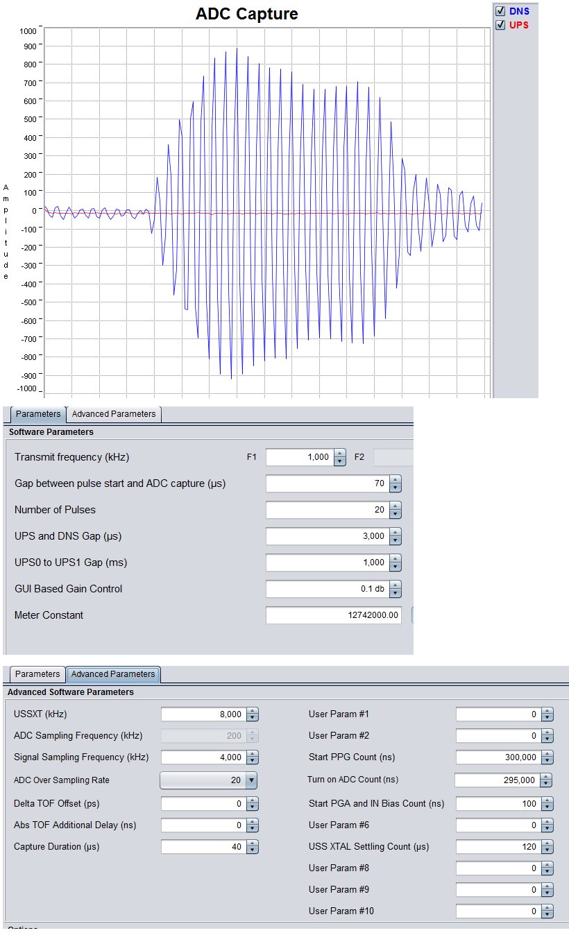
      I tested the project named USSSWLIB_template_example,I set the sequnceSelection to 'USS_measurement_capture_sequence_ch0',and I took a photo of my wave,

the question is TOF fo UPS is sometimes 78.3xx us,sometimes 79.3xx us,I didn't find the obvious difference in the picture.

Another qusetion is what is the function of 'signalValueThresholdCheck',I try to set it from 50 to 200,the TOF of UPS is 78.3xx or 79.3xx still.

Redards,

Wolf Bruce

  • Hi Wolf,

    Please use the demo application for measurements which is available below. This will also communicate with our GUI where you can capture the ADC waveforms. Please give this a try and let me know if things are more clear.

    software-dl.ti.com/.../index_FDS.html

    signalValueThresholdCheck is used to determine if there is some signal received by the ADC. For example, in the demo application, if no signal or low signal is detected, the red LED will illuminate to indicate an error.
  • Hi Eddie,

        Thank you for reply.

        My transducer signal is very weak, I magnify the signal.  The GUI demo  work at USS_measurement_capture_sequence_ch0_ch1 mode,not the sequence_ch0,I tried to use GUI,I can get the adc capture of UPS,but no DNS,and I can't get the TOF of UPS.

    I want to know why the TOF of UPS change between 73 and 74us?

    Best Regards

    Wolf

  • Wolf,

    Can you provide some info about your hardware? Are you using a custom board or the EVM?

    You also mention about the sequence_ch0 not working. Do you have a use case for only ch0?

    In regards to the "no UPS signal" issue, can you try changing the software to send ch1, then ch0 to determine if the signals swap?

    Can you please send a screenshot of the waveforms panel in the GUI showing the 73/74uS TOF?

    The start PGA and IN Bias Count should be set to 5000, but I don't think this is the source of your problem.

    Last, can you please try changing the signal sampling frequency to 3600 in case there could be some harmonic interference?

    Let me know the results and we will take it from there. Thanks!
  • Eddie,

    I test the project named 'USSSWLIB_template_example' on EVM and my board, they have the same problem.

    The signal is so weak that the amplifiers inside the MCU are not enough to magnify it to the right intensity.So I have to add a  VGA board to amplify the tiny signals,and this board have no channel switching circuit,so I can  make a test for only ch0.

    I modify the demo GUI project from sequence_ch0_ch1 to ch0,and sample frequency is 3600,in the picture above you can see the GUI adc capture on the left,the real shape on the right,and GUI can't get the TOF.

    and this is the pictrue of sample frequency 4000,at this time, adc capture on the left, TOF display from GUI on the right.but you can see the data has a big wobble.

    If I use the unmodified project of GUI_demo,I can get the adc capture waveform looks right, the picture can be seen in my last post.at that time ,the TOF data can't be  obtained.

    Is it that my magnify the waveform signal-to-noise ratio is not good enough?

    or my configuration is wrong somewhere?

  • Can anyone help me?

  • Hello,

    Sorry for the delay. In your capture with 3600kHz sampling, the signal is too large. Please reduce the gain to get the ADC counts down to +/-900 counts. Let me know if that changes the TOF behavior.

    Also, I am curious about the setup you have which requires external VGA. Is this a very large pipe size or is there some other attenuation factor which is requiring this amplifier?

**Attention** This is a public forum