This thread has been locked.

If you have a related question, please click the "Ask a related question" button in the top right corner. The newly created question will be automatically linked to this question.

CCS/MSP432P401R: Is it possible to do PWM in Burst mode?

Part Number: MSP432P401R

Tool/software: Code Composer Studio

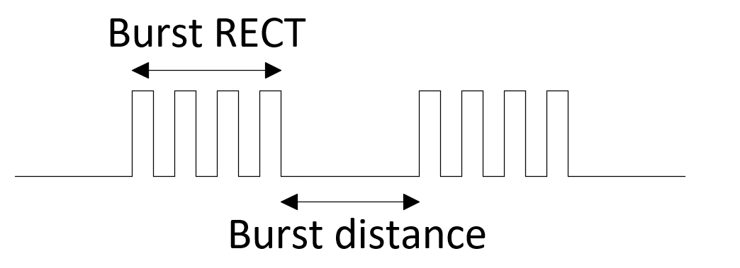
Hi i want to use the MSP432 PWM in burst mode, is this possible?

If not, is there any IC from TI that can make me a Square Wave in Burst mode?

I need to set the amount of square in Burst and the distance time from one to the other.

  • Hello Michael,

    When you say burst mode, could you describe the behavior? Do you want the PWM to continuously o/p signals without CPU intervention?

    Thanks,
    Sai
  • Hi Michael,

    which burst mode do you mean?

    Timer_A generated PWM should not be affected by GRAM burst operations nor by DMA burst transfers.

    Did i missed something from MSP432P4xx Tech. Ref. Manual (SLAU356H)?

    Regards,

    Tomasz

    MSP432P4xx
    SimpleLink
    ™ Microcontrollers
    Technical
    Reference
    Manual
  • Hi,

    i want to use PWM Timer from MSP432 to generate Bursts like this:

    Can the PWM Timer driver from MSP432 do this? If not, is there a way that MSP432 can do this?

    And if the MSp432 cannot do this, is there a IC from TI that can do Burst Signals?

  • You would have to use another timer as a gate. An external AND gate could be used to create the burst.
  • Hi Keith,

    thanks for you answer. I can use 2 PWMs.
    One with normal Frequency, and the other timer PWM to controll the "Burst Rect"(amount of rectangle on signal) and "Burst distance"(amount of time between each burst)
    I think that would work and it doenst need the CPU to to anything.
  • Hi Michael,

    thanks for explanation!

    If a15 bits resolution for PWM and Burst, all together, satisfies  you,
    I have something you might like.
    Only 1 timer and no external logic.

    Just set the output mode to 010 Toggle/Reset.

    The output is toggled when the timer counts to the TAxCCRn value.
    It is reset when the timer counts to the TAxCCR0 value.

    TAxCCRn assings your RECT value.
    TAxCCR0 assigns your RECT + distance value.

    Does it resolve your issue?

    If yes, please mark this thread as answered.

    I would remember your burst forever :-)

    Kind regards,

    Tomasz

    The output
    is toggled
    when
    the timer
    counts
    to the TAxCCRn
    value.
    It is reset
    when
    the
    timer
    counts
    to the TAxCCR0
    value.
  • Hi,
    one remark to my previous post.
    I mentioned a 15 bits resolution.
    If I am not wrong, an output would be toggled with a half of a "Timer Clock" frequency.
    Figure 19-1. Timer_A Block Diagram, SLAU356H Tech. Ref. Manual.


    Regards,

    Tomasz
  • Michael, Keith,

    I have posted question related to Timer_A documentation.

    e2e.ti.com/.../684588

    rgds/tmk
  • Hi Tomasz,

    i like your idea better because i can use the MSP432 only to do the burst.

    I am having some trouble setting the two timers to do the Burst.

    You can find attached my code.

    /* --COPYRIGHT--,BSD
     * Copyright (c) 2017, Texas Instruments Incorporated
     * All rights reserved.
     *
     * Redistribution and use in source and binary forms, with or without
     * modification, are permitted provided that the following conditions
     * are met:
     *
     * *  Redistributions of source code must retain the above copyright
     *    notice, this list of conditions and the following disclaimer.
     *
     * *  Redistributions in binary form must reproduce the above copyright
     *    notice, this list of conditions and the following disclaimer in the
     *    documentation and/or other materials provided with the distribution.
     *
     * *  Neither the name of Texas Instruments Incorporated nor the names of
     *    its contributors may be used to endorse or promote products derived
     *    from this software without specific prior written permission.
     *
     * THIS SOFTWARE IS PROVIDED BY THE COPYRIGHT HOLDERS AND CONTRIBUTORS "AS IS"
     * AND ANY EXPRESS OR IMPLIED WARRANTIES, INCLUDING, BUT NOT LIMITED TO,
     * THE IMPLIED WARRANTIES OF MERCHANTABILITY AND FITNESS FOR A PARTICULAR
     * PURPOSE ARE DISCLAIMED. IN NO EVENT SHALL THE COPYRIGHT OWNER OR
     * CONTRIBUTORS BE LIABLE FOR ANY DIRECT, INDIRECT, INCIDENTAL, SPECIAL,
     * EXEMPLARY, OR CONSEQUENTIAL DAMAGES (INCLUDING, BUT NOT LIMITED TO,
     * PROCUREMENT OF SUBSTITUTE GOODS OR SERVICES; LOSS OF USE, DATA, OR PROFITS;
     * OR BUSINESS INTERRUPTION) HOWEVER CAUSED AND ON ANY THEORY OF LIABILITY,
     * WHETHER IN CONTRACT, STRICT LIABILITY, OR TORT (INCLUDING NEGLIGENCE OR
     * OTHERWISE) ARISING IN ANY WAY OUT OF THE USE OF THIS SOFTWARE,
     * EVEN IF ADVISED OF THE POSSIBILITY OF SUCH DAMAGE.
     * --/COPYRIGHT--*/
    /*******************************************************************************
     * MSP432 Timer_A - Variable PWM
     *
     * Description: In this example, the Timer_A module is used to create a precision 
     * PWM with an adjustable duty cycle. The PWM initial period is 200 ms and is
     * output on P2.4. The initial duty cycle of the PWM is 10%, however when the
     * button is pressed on P1.1 the duty cycle is sequentially increased by 10%.
     * Once the duty cycle reaches 90%, the duty cycle is reset to 10% on the
     * following button press.
     *
     *                MSP432P401
     *             ------------------
     *         /|\|                  |
     *          | |                  |
     *          --|RST         P1.1  |<--Toggle Switch
     *            |                  |
     *            |                  |
     *            |            P2.4  |--> Output PWM
     *            |                  |
     *            |                  |
     *
     *******************************************************************************/
    /* DriverLib Includes */
    #include <ti/devices/msp432p4xx/driverlib/driverlib.h>
    
    /* Standard Includes */
    #include <stdint.h>
    #include <stdbool.h>
    
    //![Simple Timer_A Config]
    /* Timer_A PWM Configuration Parameter */
    Timer_A_PWMConfig pwmConfig =
    {
            TIMER_A_CLOCKSOURCE_SMCLK,
            TIMER_A_CLOCKSOURCE_DIVIDER_3,//8MHz= TIMER_A_CLOCKSOURCE_DIVIDER_3 4MHz=TIMER_A_CLOCKSOURCE_DIVIDER_6 2MHz=TIMER_A_CLOCKSOURCE_DIVIDER_12
            1,
            TIMER_A_CAPTURECOMPARE_REGISTER_1,
            TIMER_A_OUTPUTMODE_TOGGLE_SET,
            1
    };
    Timer_A_PWMConfig pwmConfig1 =
    {
            TIMER_A_CLOCKSOURCE_SMCLK,
            TIMER_A_CLOCKSOURCE_DIVIDER_3,//8MHz= TIMER_A_CLOCKSOURCE_DIVIDER_3 4MHz=TIMER_A_CLOCKSOURCE_DIVIDER_6 2MHz=TIMER_A_CLOCKSOURCE_DIVIDER_12
            1,
            TIMER_A_CAPTURECOMPARE_REGISTER_2,
            TIMER_A_OUTPUTMODE_TOGGLE,
            1
    };
    Timer_A_PWMConfig pwmConfig2 =
    {
            TIMER_A_CLOCKSOURCE_SMCLK,
            TIMER_A_CLOCKSOURCE_DIVIDER_1,//8MHz= TIMER_A_CLOCKSOURCE_DIVIDER_3 4MHz=TIMER_A_CLOCKSOURCE_DIVIDER_6 2MHz=TIMER_A_CLOCKSOURCE_DIVIDER_12
            480,
            TIMER_A_CAPTURECOMPARE_REGISTER_1,
            TIMER_A_OUTPUTMODE_TOGGLE_RESET,
            360
    };
    /*TIMER_A_OUTPUTMODE_SET=HIGH
    TIMER_A_OUTPUTMODE_TOGGLE_RESET=16MHz invert
    TIMER_A_OUTPUTMODE_SET_RESET=16MHz invert
    TIMER_A_OUTPUTMODE_TOGGLE =8MHz
    TIMER_A_OUTPUTMODE_RESET=0MHz
    TIMER_A_OUTPUTMODE_TOGGLE_SET=16MHz
    TIMER_A_OUTPUTMODE_RESET_SET= 16MHz
     *
     */
    //![Simple Timer_A Config]
    
    int main(void)
    {
        /* Halting the watchdog */
        MAP_WDT_A_holdTimer();
    
        GPIO_setAsPeripheralModuleFunctionOutputPin(GPIO_PORT_PJ, GPIO_PIN2 | GPIO_PIN3, GPIO_PRIMARY_MODULE_FUNCTION);
        CS_setExternalClockSourceFrequency(32768,48000000);
        PCM_setCoreVoltageLevel(PCM_VCORE1);
        FlashCtl_setWaitState(FLASH_BANK0, 2);
        FlashCtl_setWaitState(FLASH_BANK1, 2);
        CS_startHFXT(false);
    
        CS_initClockSignal(CS_MCLK , CS_HFXTCLK_SELECT, CS_CLOCK_DIVIDER_1);
        CS_initClockSignal(CS_SMCLK, CS_HFXTCLK_SELECT, CS_CLOCK_DIVIDER_1);// MHz
    
        /* Configuring GPIO2.4 as peripheral output for PWM  */
       // MAP_GPIO_setAsPeripheralModuleFunctionOutputPin(GPIO_PORT_P2, GPIO_PIN4,GPIO_PRIMARY_MODULE_FUNCTION);
        MAP_GPIO_setAsPeripheralModuleFunctionOutputPin(GPIO_PORT_P2, GPIO_PIN5,GPIO_PRIMARY_MODULE_FUNCTION);
        MAP_GPIO_setAsPeripheralModuleFunctionOutputPin(GPIO_PORT_P7, GPIO_PIN7,GPIO_PRIMARY_MODULE_FUNCTION);
    
    
        /* Configuring Timer_A */
        //MAP_Timer_A_generatePWM(TIMER_A0_BASE, &pwmConfig);
        MAP_Timer_A_generatePWM(TIMER_A0_BASE, &pwmConfig1);
        MAP_Timer_A_generatePWM(TIMER_A1_BASE, &pwmConfig2);
    
    
        /* Sleeping when not in use */
        while (1)
        {
            MAP_PCM_gotoLPM0();
        }
    }


    I am using two timers TIMER_A0_BASE and TIMER_A1_BASE and output separately on GPIO pins to measure and understand it with an oscilloscope.

    I am using driverlib to generate the PWM.

    Yellow: 4MHz PWM Signal

    Blue: Gate and Timing controll

    The only problem is that the are not synchronized. And how do i mixed now this two signals with one timer?

  • Hi Michael,

    Keith wrote: An external AND gate could be used to create the burst.

    Using two PWMs requires logical AND of both signals
    and looks to me that it cannot be done using MSP432 internal circuitry.
    An external AND gate might be used, an open colector based logical AND might be enough.

    If a 15-bit resolution is ok for you, just go with the toggle/reset output mode.


    rgds/tmk
  • Tomasz,

    I don't see how your solution can do the job. TAxCCR0 can set the rect+distance, and TAxCCRn can set rect, but how do you toggle the pin for pwm inside the "rect" time?
  • Andrei,

    Technical Reference Manual says:

    Output mode 010 Toggle/Reset.
    The output is toggled when the timer counts to the TAxCCRn value.
    It is reset when the timer counts to the TAxCCR0 value.
    Section 19.2.5.1 Output Modes.

    A D type latch is flip-floped by Timer Clock.
    Looak at Figure 19-1.

    Does it help?

    rgds/tmk
  • No it doesn't.

    You need to set PWM On time, PWM off time, Burst time, and Distance time. How can you achieve it? Could you provide a code snippet?
    I made some dirty working examples right now and will post them in the evening.
  • Interesting,

    do you say that in the Toggle/Reset mode the output signal is not toggled?
    Probably on Mon. evening I would have a spare time to investigate that.
  • Ok, super-quick and super-dirty example from me.

    Main idea: we use CCR0 and CCR1 ISRs, timer in up mode

    1) CCR0 is used for Rect Time and Distance Time. While we are within Distance Time we don't output any PWM, we assure that by setting CCR1 to CCR0 + 1 (so that CCR1 interrupt never hits)

    2) When we switch to Rect Time (timer overflows) we start the burst by changing CCR1 value to PWM time, and then chaging On/Off times inside the CCR1 ISR until wi hit CCR0 once more.

    /*
     * We assume SMCLK as a source ~ 3MHz hence
     * sample = 1/3MHz = 333 nSec
     * PWM On Time = 300 * sample = 100 uSec;
     * PWM Off Time = 150 * sample = 50 uSec
     * And PWM Period = 150uSec, Duty = 66.6%
     * Rect time = 3000 * sample = 1 mSec
     * Distance = 6000 * sample = 2 mSec
     */
    
    
    static uint16_t u16PwmOnTime = 300;
    static uint16_t u16PwmOffTime = 150;
    static uint16_t u16RectTime = 3000;
    static uint16_t u16DistanceTime = 6000;
    
    
    static bool bPwmHigh = false;
    static bool bBurstTime = false;
    
    int main(void)
    {
        WDT_A->CTL = WDT_A_CTL_PW | WDT_A_CTL_HOLD;
    
        P2->DIR |= BIT4;
        P2->SEL0 |= BIT4;
    
        // TACCR0
        TIMER_A0->CCTL[0] = TIMER_A_CCTLN_CCIE;
        TIMER_A0->CCR[0] = u16DistanceTime;         // We start with a distance time
    
        // TACCR1
        TIMER_A0->CCTL[1] = TIMER_A_CCTLN_OUTMOD_2 | TIMER_A_CCTLN_CCIE;
        TIMER_A0->CCR[1] = u16DistanceTime + 1;     // We should never toggle within a distance time
    
        // ACLK, cont mode
        TIMER_A0->CTL = TIMER_A_CTL_SSEL__SMCLK |  TIMER_A_CTL_MC__UP;
    
    
        SCB->SCR |= SCB_SCR_SLEEPONEXIT_Msk;    // Enable sleep on exit from ISR
    
        // Ensures SLEEPONEXIT takes effect immediately
        __DSB();
    
        // Enable global interrupt
        __enable_irq();
        NVIC->ISER[0] |= 1 << ((TA0_N_IRQn) & 31);
        NVIC->ISER[0] |= 1 << ((TA0_0_IRQn) & 31);
    
        __sleep();
        __no_operation();                       // For debugger
    }
    
    
    void TA0_0_IRQHandler(void)
    {
        TIMER_A0->CCTL[0] &= ~TIMER_A_CCTLN_CCIFG;
    
        if(bBurstTime == true)
        {
            bBurstTime = false;
            // Resetting back to distance time and "shutting up" CCR1
            TIMER_A0->CCR[0] = u16DistanceTime;
            TIMER_A0->CCR[1] = u16DistanceTime + 1;
        }
        else
        {
            bBurstTime = true;
            // Starting the burst, setting the CCR1 to PWM off time (we can also start with on - doesn't matter)
            TIMER_A0->CCR[0] = u16RectTime;
            TIMER_A0->CCR[1] = u16PwmOffTime;
            bPwmHigh = false;
        }
    }
    
    void TA0_N_IRQHandler(void)
    {
        if(TIMER_A0->CCTL[1]&TIMER_A_CCTLN_CCIFG)
        {
            TIMER_A0->CCTL[1] &= ~TIMER_A_CCTLN_CCIFG;
            if(bPwmHigh == true)
            {
                bPwmHigh = false;
                TIMER_A0->CCR[1] += u16PwmOffTime;
            }
            else
            {
                bPwmHigh = true;
                TIMER_A0->CCR[1] += u16PwmOnTime;
            }
        }
    }

    First pic: bursts (1 mSec resolution), second pic: PWM itself (50 uSec resolution).

    Keep in mind that this is not very reliable: dynamically adjust PWM within ISR.

  • Hi Andrei,

    thanks for your answer and example code.
    I have to improve it so that it doenst need any interrupt.

    If this is not possible, than i think the AND solution will be better.

  • Hi Andrei,

    i made some modification but still couldnt get it to work without interrupt but with external AND.

    To make sure the 2 timers are synchron, i use the TIMER_A1_BASE(4MHz) as "burst rectangle" generator and wire this externally as input clock for TIMER_A0_BASE.

    TIMER_A0_BASE generates also a PWM but uses TIMER_A1_BASE as clock and here i know that i am synchron. Both need to go to the AND logic IC and TIMER_A0_BASE controlls the burst time and distance.

    This code doesnt need the CPU to do any ISR to change counter and so on.

    Here is my code:

    /* DriverLib Includes */

    #include <ti/devices/msp432p4xx/driverlib/driverlib.h>

    /* Application Defines */

    #define TIMER_PERIOD 6

    #define TIMER_PERIOD_DISTANCE 12

    #define TIMER_PERIOD_BURST    16

    #define DUTY_CYCLE1 3

    #define DUTY_CYCLE2 2

    /* Timer_A UpDown Configuration Parameter */

    const Timer_A_UpDownModeConfig upDownConfig =

    {

           TIMER_A_CLOCKSOURCE_SMCLK,              // SMCLK Clock SOurce

           TIMER_A_CLOCKSOURCE_DIVIDER_1,          // SMCLK/1 = 3MHz

           TIMER_PERIOD,                           // 127 tick period

           TIMER_A_TAIE_INTERRUPT_DISABLE,         // Disable Timer interrupt

           TIMER_A_CCIE_CCR0_INTERRUPT_DISABLE,    // Disable CCR0 interrupt

           TIMER_A_DO_CLEAR                        // Clear value

    };

    /* Timer_A Compare Configuration Parameter  (PWM1) */

    const Timer_A_CompareModeConfig compareConfig_PWM1 =

    {

           TIMER_A_CAPTURECOMPARE_REGISTER_1,          // Use CCR1

           TIMER_A_CAPTURECOMPARE_INTERRUPT_DISABLE,   // Disable CCR interrupt

           TIMER_A_OUTPUTMODE_TOGGLE_SET,              // Toggle output but

           DUTY_CYCLE1                                 // 32 Duty Cycle

    };

    Timer_A_PWMConfig pwmConfig2 =

    {

           TIMER_A_CLOCKSOURCE_EXTERNAL_TXCLK,//TIMER_A_CLOCKSOURCE_EXTERNAL_TXCLK,

           TIMER_A_CLOCKSOURCE_DIVIDER_1,//8MHz= TIMER_A_CLOCKSOURCE_DIVIDER_3 4MHz=TIMER_A_CLOCKSOURCE_DIVIDER_6 2MHz=TIMER_A_CLOCKSOURCE_DIVIDER_12

           TIMER_PERIOD_BURST,

           TIMER_A_CAPTURECOMPARE_REGISTER_1,

           TIMER_A_OUTPUTMODE_TOGGLE_RESET,

           TIMER_PERIOD_DISTANCE

    };

    int main(void)

    {

       /* Stop WDT  */

       MAP_WDT_A_holdTimer();

       GPIO_setAsPeripheralModuleFunctionOutputPin(GPIO_PORT_PJ, GPIO_PIN2 | GPIO_PIN3, GPIO_PRIMARY_MODULE_FUNCTION);

       CS_setExternalClockSourceFrequency(32768,48000000);

       PCM_setCoreVoltageLevel(PCM_VCORE1);

       FlashCtl_setWaitState(FLASH_BANK0, 2);

       FlashCtl_setWaitState(FLASH_BANK1, 2);

       CS_startHFXT(false);

       CS_initClockSignal(CS_MCLK , CS_HFXTCLK_SELECT, CS_CLOCK_DIVIDER_1);

       CS_initClockSignal(CS_SMCLK, CS_HFXTCLK_SELECT, CS_CLOCK_DIVIDER_1);// MHz

       /* Setting P7.7 and P7.6 and peripheral outputs for CCR */

       MAP_GPIO_setAsPeripheralModuleFunctionOutputPin(GPIO_PORT_P7, GPIO_PIN7, GPIO_PRIMARY_MODULE_FUNCTION);

       MAP_GPIO_setAsPeripheralModuleFunctionOutputPin(GPIO_PORT_P2, GPIO_PIN4, GPIO_PRIMARY_MODULE_FUNCTION);

       MAP_GPIO_setAsPeripheralModuleFunctionInputPin(GPIO_PORT_P7, GPIO_PIN1, GPIO_PRIMARY_MODULE_FUNCTION);

       /* Configuring Timer_A1 for UpDown Mode and starting */

       MAP_Timer_A_configureUpDownMode(TIMER_A1_BASE, &upDownConfig);

       MAP_Timer_A_startCounter(TIMER_A1_BASE, TIMER_A_UPDOWN_MODE);

       MAP_Timer_A_initCompare(TIMER_A1_BASE, &compareConfig_PWM1);

       MAP_Timer_A_generatePWM(TIMER_A0_BASE, &pwmConfig2);

       /* Sleeping when not in use */

       while (1)

       {

           MAP_PCM_gotoLPM0();

       }

    }

    Obs: For AND Logic Chip i found SN74AHC1G09 from TI

  • Andrei,

    of course you are right.
    Great that you raised the problem.
    Thanks to you Michael could go in a right direction and do some advances.

    Last Fri., thanks to you, I found how much I misunderstood operations of Timer_A.

    rgds/tmk
  • Michael,

    I am sorry for a wrong hint.

    This evening I tried some alternatives for you.
    I do not see any logical AND operations on signal paths between Timer_A and Comp_E moduls.

    Looks to me that an external AND is the only choice.


    Good luck,

    Tomasz
  • Hi Tomasz,

    no worries and thanks for helping me.
  • Hi Michael,

    I have looked at MSP430FR5994 and its Programmable Pulse Generator.
    And still no concet how to implement PWM busrt with no MPU cycles.

    Please, take a 5 minutes and look at this: google for this one: 41631B.pdf
    Both MSP 16/32-bits architectures have a lot of multiplexers, PIN mappings, etc.
    however there is no MCU off loading glue between them.
    Adding some number of MUXes and a few gates/lateches could give very huge PCB space and power savings.
    Assuming that MSPs business is power saving driven, that is really pity not having CLCs blocks.

    Any patent restrictions?
    I do not thing so.

    Go ahead!
    rgds/tmk

    P.S. Do you have any recommendation for a partial screen capture tool?
  • Michael,

    Indeed, your solution is the most proper way to reliably do the job.

    Anyway, you raised an interesting problem that can be solved differently depending on the compromise you can have between no cpu intervention versus no external parts.

    Tomasz,

    That's a good question. Maybe someone from MSP digital design team can shed some light on this. Thanks for the interesting note reference.
  • Andrei, Michael, I
    I am having a little trouble following the discussion. What aspect are you asking for some light to be shed on?

    With respect to the original question, I have used a combination of the timer/dma/eusci to do something similar. The burst is simply a SPI output (MOSI or the CLK), which is loaded by the DMA (scatter-gather which loads two bytes) which is in turn triggered by the timer.

    Regards,
    Chris
  • Hi Chris,

     i didnt understand your question "What aspect are you asking for some light to be shed on? "

    My question was simple on how to do a BURST signal and controll the amount of rectangle and time(distance) between them.

    The best way for me now is to use two timers and use an external AND to combine it to a BURST. 

**Attention** This is a public forum