This thread has been locked.

If you have a related question, please click the "Ask a related question" button in the top right corner. The newly created question will be automatically linked to this question.

CCS/MSP430F6736: Problem in lcd module

Part Number: MSP430F6736

Tool/software: Code Composer Studio

Hi,

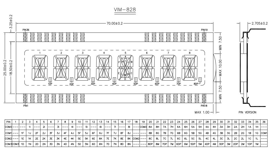
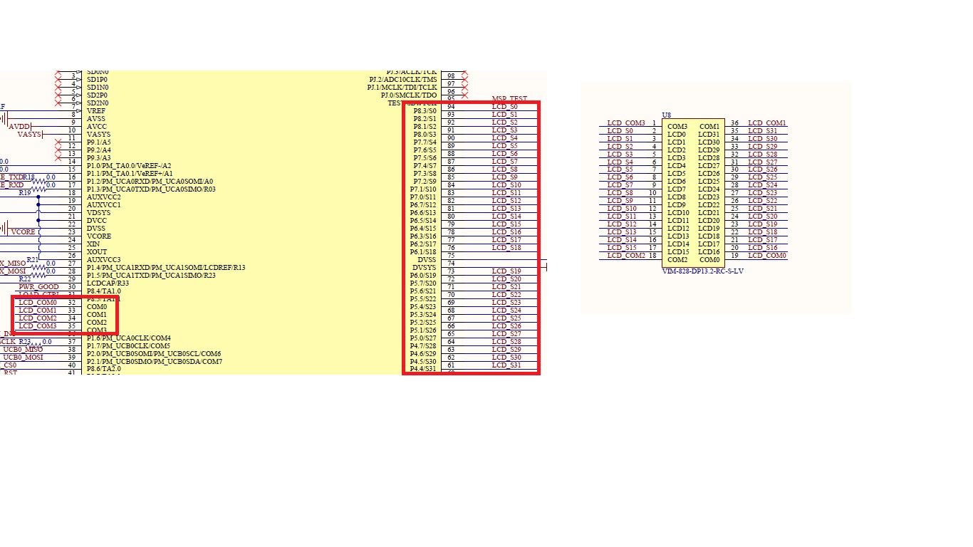
I have a custom board having msp430f6736 and 14 segment LCD display(VIM-828-DP13.2-RC-S-LV).i can't print character in 6,7 positions but can print characters in all other positions from 1 to 8 except 6 and 7.

i don't know why.can any one solve this .(i did the code with lcd c module in this controller, configuration shown below).

//////////initialisation////////

LCDCCTL0 = LCDDIV_31 | LCDPRE_1 | LCD4MUX | LCDON;

//Charge pump generated internally at 2.96V, external bias (V2-V4) generation
//Internal reference for charge pump
LCDCVCTL = LCDCPEN | VLCD_2_96;
REFCTL0 &= ~REFMSTR;

LCDCPCTL0 = 0xFFFF; //Select LCD Segments 4-5
LCDCPCTL1 = 0xFFFF; //

///////////////////////////////////////////////printing A

LCDM1=BIT1|BIT2|BIT6;
LCDM16=BIT0|BIT1|BIT2|BIT5;

///////////////////////////////////clearing

LCDM1=00x00;
LCDM16=0x00;

  • Hello,

    Thank you for your detailed post. I suspect that the solution here is selecting the correct LCDMx bits for desired characters.

    To get started, refer to the VIM-828-DP13.2-RC-S-LV datasheet where the LCD memory map is provided (shown below).

    Next, refer to Figure 35-2 in the MSP430F6736 User's Guide where the LCD memory map is provided for 4-mux mode for (less than or equal to) 160 segments (shown below). Notice that this table is just transposed compared to the VIM-828 table.

    Now, let's display a "0" on character 6. Looking at the LCD memory map for the VIM-828, you'll want segments 6A, 6B, 6C, 6D, 6E, and 6F. These segments correspond to Pins 24 and 12. Looking at the MSP430F6736 LCD memory map, these pins correspond to the lower four bits in the registers LCDM13 and LCDM7.

    // Print a zero on Character 6
    
    LCDM7 = BIT1 | BIT2 | BIT3;     // COM1, COM2, COM3
    LCDM13 = BIT0 | BIT1 | BIT2;   // COM0, COM1, COM2

    For more information about how LCD's work, please refer to our Designing With MSP430™ MCUs and Segment LCDs application report.

    Hope this helps!

    Regards,

    James

    MSP Customer Applications

  • Hi James,
    Thanks for your great support.The details where correct as per you shown but it's not the right thing for me .i explain in detail
    in my design com0,com1,com2 and com3 where connected to the lcd modules pin19,pin36,pin18,pin1 .
    and from my observation LCDM1 and LCDM16 for first position
    LCDM2 and LCDM15 for second position and correspondingly.
    because starting s0 in pin2  of lcd and s31 in pin 35 . and the idea get from user guide page 922.(pin 2 ,pin3 and pin34,pin 35 for first position ,the corresponding pins in mcu s0,s1 and s30, s31 so from the page 922 s0, s1 memmory reg is LCDM1 and s30, s31 memmory reg is LCDM16)
    on this way i print characters in every positions and works great but when i put a value in the 6 th and 7th position the lcd will not work properly some times the other field characters disappeared or some wrong lines where open.I doubted two things either lcd is damaged or my configuration is wrong .I need an expert opinion that's why i ask you .please solve it properly .

    Aju.S

  • Hello Aju,

    You mentioned that you're using a custom board with the MSP430F6736. Can you please confirm that you've made the correct connections between the MCU and the LCD on your schematic and hardware? It gets confusing here since the LCD does not have Pin 0 whereas the MCU has S0. Perhaps, the connections are wrong (or just inconsistent), so when configuring the LCDMx registers, you're not seeing the correct results.

    Are you connecting S1 of the MCU to Pin 1 of the LCD? Pin 1 is COM3 on the LCD, and the MCU has dedicated COMx pins for these connections. It would be helpful if you could share the LCD portion of your schematic or list the connections between the MCU and LCD.

    Regards,

    James

    MSP Customer Applications
  • I would highly recommend carefully reading through Section 5 LCD Layout and Software Considerations in the previously-mentioned Designing With MSP430™ MCUs and Segment LCDs application report. It's a helpful reference for mapping the LCD pins to the MCU and also hardware and software layout considerations.

    I suspect that if you follow the guidelines in Section 5, you'll resolve your issue.

    Regards,

    James

    MSP Customer Applications

  • Hi james,

    thanks for your valuable support ,i attached my board's schematics here (for LCD only).Please verify  and support me to correct the issue.

  • Hello,

    Thanks for sharing your schematic. The connections seem correct as long as you realize that your pins (and therefore your LCD memory map) are shifted by two or four relative to your Sx connections. For example, S0 is connected to Pin 2, S1 to Pin 3, etc. (difference of 2), but then S16 is connected to Pin 20, S17 to Pin 21, etc. (difference of 4 now). You'll need to account for this when using the LCDMx registers.

    In my code above where I was using LCDM7 and LCDM13, I was assuming that you connected S2 to Pin 2, S3 to Pin 3, etc., so you'll need to change this accordingly. I suspect that the issue comes down to mapping the pins to the segments and understanding the offsets.

    Regards,

    James

    MSP Customer Applications

  • Hi James ,
    Thanks for your reply,
    the memory register that i used is

    for 1st position(LCDM1,LCDM16)
    for 2nd position(LCDM2,LCDM15)
    for 3rd position(LCDM3,LCDM14)
    for 4th position(LCDM4,LCDM13)
    for 5th position(LCDM5,LCDM12)
    for 6th position(LCDM6,LCDM11)
    for 7th position(LCDM7,LCDM10)
    for 8th position(LCDM8,LCDM9)

    is it correct ?.when i tried this way i can print characters in all position except 6th and 7th.my configurations are shown in first question.i hope you can solve this easily .


    Aju S
  • Hello,

    Thanks for the helpful summary. Looking at everything, your LCD/MCU connections and register configurations all seem fine and mapped correctly. With this confirmed, let's move on.

    Next, I took a look at the erratasheet for the MSP430F6736 and discovered there are two LCD related errata, LCDB5 and LCDB6. Please take a look at both of these below.

    For the issue that you're observing, I suspect that LCDB6 is causing the issue. Per its workaround, it says "do not modify VLCDx and/or LCDCPEN bits in LCDCVCTL register while LCDON = '1' ". Looking at the code in your initial post, I see that LCDCVCTL is getting modified when LCDON = '1'. According to the Description, this could cause corrupted LCD output. Please implement this workaround and let me know if it resolves this issue before proceeding.

    Regards,

    James

    MSP Customer Applications

  • Hi ,
    sorry for the late reply ,thanks for your support.
    now i changed my configuration

    // Setup LCD_C
    // LCD_FREQ = ACLK/32/4, LCD Mux 4
    LCDCCTL0 = LCDDIV_31 | LCDPRE_1 | LCD4MUX ;

    //Charge pump generated internally at 2.96V, external bias (V2-V4) generation
    //Internal reference for charge pump
    LCDCVCTL = LCDCPEN | VLCD_2_96;
    REFCTL0 &= ~REFMSTR;

    LCDCPCTL0 = 0xFFFF;
    LCDCPCTL1 = 0xFFFF; //

    LCDCCTL0|= LCDON;

    but still have the same problem .do you have any suggestion to this ?
  • Hello,

    I don't see anything wrong with your configuration code, so I'm suspecting that it's a hardware issue. Have you checked to see if there are any wrong connections, shorts, damaged LCD, etc.? Have you tried replacing the LCD? Have you ever seen segments displayed on the 6th and 7th characters (even if it's noisy/wrong) or have they never been displayed?

    Regards,

    James

    MSP Customer Applications
  • Hi james ,
    Thanks for your support.
    I'm also suspecting the hardware but if i put 0xFF value to all memory register then the 6th and 7th position will also showing full segment on.if i pass a value to register for printing 'A' then have some noisy 'A' on that position and same noise on every place .If i put a value to 6th and 7th then i cant print any character on other place (if i send any value ,the places will always blank until i put 0x00 to all places) .


    Aju
  • Again, I suspect this is a hardware issue. Double-check the connections are correct and the LCD is not damaged or there's not a short somewhere. If you're getting the 6th and 7th characters to show up, figure out which memory registers are displaying them and see if your (actual) connections match those registers. This is definitely a strange issue.

    Regards,

    James

    MSP Customer Applications

**Attention** This is a public forum