This thread has been locked.

If you have a related question, please click the "Ask a related question" button in the top right corner. The newly created question will be automatically linked to this question.

RTOS/MSP432P401R: SD card - 30mA consumption

Part Number: MSP432P401R

Tool/software: TI-RTOS

Hello,

I'm designing a ULP system, unfortunately I found out that after using the SD card it stays in a state that consumes an abnormal number of energy like 30mA. Putting the card out of the mounter consumption goes down to numbers before using it.

I've tried multiple cards and with all of them the problem persist...

It is possible to shut down/power down/put in idle state the SD card? 

SDK:
Simplelink 2.00, fatsdraw example.

Thank you
Miha

  • Hello Miha,

    SD Card when shutdown by using IDLE command still will consume sufficiently high power w.r.t to the MCU. The ideal solution would be to have a load switch that powers the SD Card with a GPIO to control the supply to the SD Card.
  • Hi Amit,

    But cans I send a IDLE command or this should be controlled by drivers ?

    Regards
  • Hello,

    either NOR or NAND cards require 9-12V for write/erase and do that voltage using a non efficient capacitor charge pump.
    Some cards need up to 100 mA for write/erase.
    Some cards go into a sleep mode after being idle for a few msec. and during and then they drain below 250 micro amps.
    I do remember that some SanDisk SD Cards have an automatic entrance and exit from a sleep mode.
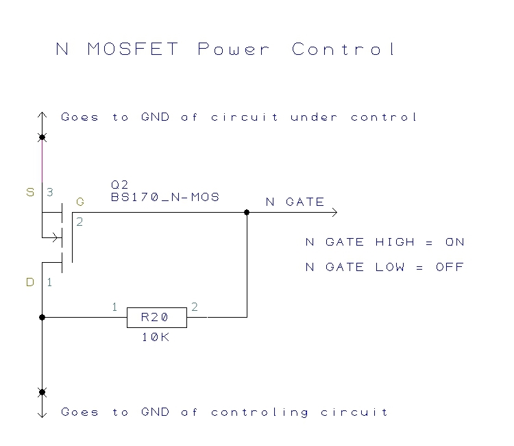
    Probably the most robust solution is to gate a card with an N-MOS transistor driven by one of GPIOs.

  • Hello Miha

    With the number of counterfeit SD Cards in the market it is difficult to state a current number tat you will be able to achieve. As Tomasz pointed you need to make sure that the card is an authentic card from the manufacturer and if the current number of 250 uA is acceptable then we could help with the sequencing of events for Idle mode. Else use of a load switch and re-init is the most viable option.
  • Thanks to google and someone who did the job:

  • Hello Amit,

    Thank you for the help.

    I have different cards but I would like to use a sandisc in the production. The 250uA would be perfect because right now I've got stack at 30mA consumption. I have also a tiny solar panel on the board and it charges the battery really well.

    The main problem is that I already put the PCB in the preproduction phase(for testing few board) and I cannot access the SD card anymore to replace it. 
    Right now I would like to save the 10PCBs that are ready to go in the production, later on I will switch to spi ram or put an switch for the SD.

    So if you are so kind to let me know how can I shoot down the SD card I would be really grateful.


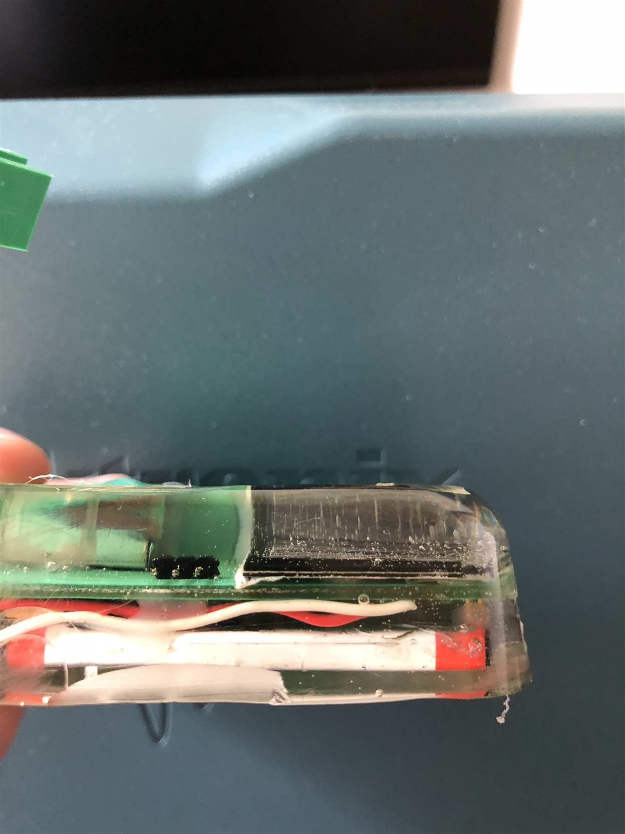
    I'm attaching an image of an test board(not the current one) and the case... so you can see why I cannot change the SD card :D

    Thank you for the help

  • Thank you for the picture and idea.
  • Hello Miha,

    Looking at the documentation for the Fat File System, there is no specific command to do so. You can try closing and unmounting the drive using f_close and f_unmount
  • After f_close() and f_unmount() put the MCU lines interfacing with the card into a high impedance.
    The card should feel as disconnected and an automatic sleep mode should start.
  • unfortunately I cannot put the pins in high impedance state.

    I've tried to manually config the CS(the latest drivers handles CS on their own..).

    What I found out is that if I read something after I put the CS in the HI(deselect) the card goes to idle.
    There are some solutions on the internet that you have to put 80clocks at the end to put the card in idle so it must be something.

    really strange... 

    Thank you for the help

  • Could you explain why you cannot put lines in high impedance, please?
    Analyzing SD card driver should be possible to find a way how to put lines in the high impedance state and how to restore lines state before coming back to the driver function calls.

    I agree with you that the SD card market is a real mess.
    If possible, focus on a well recognized producers and fake products.
  • If I understand correctly putting the PINS in the high impedance would mean that I reset the functionality of them.

    Since the pins are configured like this:

    *
     * NOTE: The SPI instances below can be used by the SD driver to communicate
     * with a SD card via SPI.  The 'defaultTxBufValue' fields below are set to 0xFF
     * to satisfy the SDSPI driver requirement.
     */
    const SPIMSP432DMA_HWAttrsV1 spiMSP432DMAHWAttrs[MSP_EXP432P401R_SPICOUNT] = {
        {
            .baseAddr = EUSCI_B0_BASE,
            .bitOrder = EUSCI_B_SPI_MSB_FIRST,
            .clockSource = EUSCI_B_SPI_CLOCKSOURCE_SMCLK,
            .defaultTxBufValue = 0xFF, //0xFF
            .dmaIntNum = INT_DMA_INT1,
            .intPriority = (~0),
            .rxDMAChannelIndex = DMA_CH1_EUSCIB0RX0,
            .txDMAChannelIndex = DMA_CH0_EUSCIB0TX0,
            .clkPin  = SPIMSP432DMA_P1_5_UCB0CLK,
            .simoPin = SPIMSP432DMA_P1_6_UCB0SIMO,
            .somiPin = SPIMSP432DMA_P1_7_UCB0SOMI,
            .stePin  = SPIMSP432DMA_P1_4_UCB0STE,
            .pinMode  = EUSCI_SPI_3PIN,
            .minDmaTransferSize = 10
        },
        {
            .baseAddr = EUSCI_B2_BASE,
            .bitOrder = EUSCI_B_SPI_MSB_FIRST,
            .clockSource = EUSCI_B_SPI_CLOCKSOURCE_SMCLK,
            .defaultTxBufValue = 0xFF,
            .dmaIntNum = INT_DMA_INT2,
            .intPriority = (~0),
            .rxDMAChannelIndex = DMA_CH5_EUSCIB2RX0,
            .txDMAChannelIndex = DMA_CH4_EUSCIB2TX0,
            .clkPin  = SPIMSP432DMA_P3_5_UCB2CLK,
            .simoPin = SPIMSP432DMA_P3_6_UCB2SIMO,
            .somiPin = SPIMSP432DMA_P3_7_UCB2SOMI,
            .stePin  = SPIMSP432DMA_P3_4_UCB2STE,
            .pinMode  = EUSCI_SPI_3PIN,
            .minDmaTransferSize = 10
        },
        {
            .baseAddr = EUSCI_A1_BASE,
            .bitOrder = EUSCI_A_SPI_MSB_FIRST,
            .clockSource = EUSCI_A_SPI_CLOCKSOURCE_SMCLK,
            .defaultTxBufValue = 0xFF,
            .dmaIntNum = INT_DMA_INT2,
            .intPriority = (~0),
            .rxDMAChannelIndex = DMA_CH3_EUSCIA1RX,
            .txDMAChannelIndex = DMA_CH2_EUSCIA1TX,
            .clkPin  = SPIMSP432DMA_P2_5_UCA1CLK,
            .simoPin = SPIMSP432DMA_P2_6_UCA1SIMO,
            .somiPin = SPIMSP432DMA_P2_7_UCA1SOMI,
            .stePin  = SPIMSP432DMA_P2_3_UCA1STE,
            .pinMode  = EUSCI_SPI_4PIN_UCxSTE_ACTIVE_LOW,
            .minDmaTransferSize = 10
        },
        {
            .baseAddr = EUSCI_B2_BASE,
            .bitOrder = EUSCI_B_SPI_MSB_FIRST,
            .clockSource = EUSCI_B_SPI_CLOCKSOURCE_SMCLK,
            .defaultTxBufValue = 0xFF,
            .dmaIntNum = INT_DMA_INT3,
            .intPriority = (~0),
            .rxDMAChannelIndex = DMA_CH5_EUSCIB2RX0,
            .txDMAChannelIndex = DMA_CH4_EUSCIB2TX0,
            .clkPin  = SPIMSP432DMA_P3_5_UCB2CLK,
            .simoPin = SPIMSP432DMA_P3_6_UCB2SIMO,
            .somiPin = SPIMSP432DMA_P3_7_UCB2SOMI,
            .stePin  = SPIMSP432DMA_P2_4_UCB2STE,
            .pinMode  = EUSCI_SPI_4PIN_UCxSTE_ACTIVE_LOW,
            .minDmaTransferSize = 10
        }
    };


    How can I change the state of the pins outside of the drivers? 

    I will try to go deeper in the drivers, but the changes that I made right now(in theSDSPI.c) didn't affected the behaviour of the drivers. Should I compile the fat drivers separately? 

    Thank you
    Miha

  • I do not have a card reader booster and that is why I cannot recreate your hardware configuration with my MSP432P401R.

    Many times I did tricks like this one.

    TI UART driver does not allow to change UART speed after being opened with a function UART_open().

    However it is possible to change an UART speed, do something, restore an original speed and back to the UART driver functions.

    To do that safely only one thread might have access to the particular UART.

    The exclusive access is a must!

    Code example:

    uint32_t UART_SetBaudRate(UART_Handle handle, uint32_t baudRate, int chkFlag)
    {
        UARTCC26XX_Object           *object;
        UARTCC26XX_HWAttrsV2 const  *hwAttrs;
        Types_FreqHz    freq;
        uint32_t        baudRateOld, ui32BRDI, ui32BRDF, ui32PERDMACLK, ui32ClkDiv;
        uint32_t        ui32Tmp;
        volatile uint32_t   ui32LCRH1, ui32LCRH2, ui32LCRHtmp, ui32ParMod;
    
        /* Get the pointer to the object and hwAttrs + save baud rate */
        object = handle->object;
        hwAttrs = handle->hwAttrs;
        baudRateOld = object->baudRate;
    
        /* Set new baud rate */
        object->baudRate = baudRate;
        BIOS_getCpuFreq(&freq);
    
        /* System initialization should be checked to get proper values for PERDMACLK & ClkDiv */
        ui32PERDMACLK = freq.lo;
        ui32ClkDiv = 16;
    
        ui32Tmp = ui32ClkDiv * baudRate;
        ui32BRDI = ui32PERDMACLK / (ui32Tmp);
        ui32BRDF = ((((ui32PERDMACLK - (ui32BRDI * ui32Tmp)) << 7) + 1) / (ui32Tmp)) >> 1;
    
        /* Check BRDI & BRDF dividers */
        if (chkFlag)
            if ( (ui32BRDI < 1 || ui32BRDI > 0xFFFF) || ( ui32BRDI == 0xFFFF && !ui32BRDF ) )
                System_abort("Unsupported baud rate\n");
    
        HWREG(hwAttrs->baseAddr + UART_O_IBRD) = (HWREG(hwAttrs->baseAddr + UART_O_IBRD) & ~UART_IBRD_DIVINT_M) | (ui32BRDI & UART_IBRD_DIVINT_M);
        HWREG(hwAttrs->baseAddr + UART_O_FBRD) = (HWREG(hwAttrs->baseAddr + UART_O_FBRD) & ~UART_FBRD_DIVFRAC_M) | (ui32BRDF & UART_FBRD_DIVFRAC_M);
    
        /* Rewrite to LCRH register with no changes. This gent form is used to avoid 'Assignment to itself Error/Warning */
        /* CCS v. 7.4.00015: Window->Preferences->'C/C++'/Code Analysis->Assignment to itself->Severity: change to Warning does not change Error to Warning */
        /* Even more, the statement: */
        /* HWREG(hwAttrs->baseAddr + UART_O_LCRH) = HWREG(hwAttrs->baseAddr + UART_O_LCRH); */
        /* is commented out using '//' however the Error still exist! */
        HWREG(hwAttrs->baseAddr + UART_O_LCRH) = ( HWREG(hwAttrs->baseAddr + UART_O_LCRH) & ~UART_LCRH_PEN_M ) | UARTParityModeGet(hwAttrs->baseAddr);
    
        return baudRateOld;
    }

    I do an exclusive lock on the resources, in this particular case on my UART channel.
    I call my UART_SetBaudRate().
    I save the original baud rate.
    I do something.
    I restore the original baud rate calling UART_SetBaudRate() with the saved value.
    Then I release the lock on the resources and my code may again use TI UART drivers.

    This method has one dangerous side effect, in my own opinion.
    When changing a driver version, tricks like the presented one, have to be double checked.

  • Hello Miha,

    In the latest SDK for MSP432P4 I am switching pins between Analog function and Input only mode using the example C:\ti\simplelink_msp432p4_sdk_2_10_00_14\examples\rtos\MSP_EXP432P401R\demos\tida_01575_serial (File Name vibrationCapture.c)

    Since you know when the device is to be put into Idle and in which case the SD Card will be accessed, you can call the GPIO configuration function to set the GPIO high when Idle and assign it to SPI function when Fat File system access is required.

**Attention** This is a public forum