Other Parts Discussed in Thread: MSP430FR5994, MSP430WARE
Hello dear community!
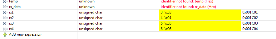
I'm trying to manage the SPI communication between the MSP430FR5994 and ADE7878 energy metering IC from Analog Devices. Everything works good while i'm testing my code on the LaunchPad . I connect the SIMO and SOMI wires together and i can see the data i'm sending on the logic analyzer and store the received data into my variables. The problem beginns when i'm interfacing the IC. I'm able to write to the registers, i can see the correct data on the logic analyzer and measure the changes on my evaluation board. When i try to preform the read operation, i can see the IC returning the correct data on the SOMI line. My problem is that i'm reading the wrong data from UCB1RXBUF, its almost always 0xFF. Sometimes when i read 1byte registers, i receive the correct value. I would be very thankful if someone could give me a hint how to manage this issue.
Thanks in advance!
Illya
#include <msp430.h>
#include <string.h>
#define DUMMY 0x00
#define CONFIG2 0xEC01
#define STATUS1 0xE503
#define RUN 0xE228
#define LAST_OP 0xE7FD
#define LAST_ADDR 0xE6FE
#define LAST_RWDATA_8 0xE7FC
#define LAST_RWDATA_16 0xE6FF
#define LAST_RWDATA_32 0xE5FF
#define PGA 0xE60F
#define COMPMODE 0xE60E
#define WTHR1 0x43AB
#define WTHR0 0x43AA
#define VLEVEL 0x43B3
#define IARMS_LRIP 0xE531
#define VARMS_LRIP 0xE531
void send (unsigned int addr, char nr_bytes, unsigned long tx_data);
unsigned volatile char byte1, byte2, byte3, byte4;
void read (unsigned int addr, char nr_bytes);
volatile unsigned char rx1, rx2, rx3, rx4;
unsigned char SPI_8(unsigned char TXdata);
unsigned volatile char TXdata;
unsigned volatile char RXdata;
void SPI_enable(void);
void SPI_disable(void);
void init(void);
volatile int counter1=0;
volatile int counter2 = 0;
int main(void)
{
WDTCTL = WDTPW | WDTHOLD; // Stop watchdog timer
P5SEL1 &= ~(BIT0 | BIT1 | BIT2); // USCI_B1 SCLK, MOSI, and MISO pin
P5SEL0 |= (BIT0 | BIT1 | BIT2); // USCI_B1 SCLK, MOSI, and MISO pin
P6DIR |= BIT3; // P6.3 OUT Csn
P3DIR &= ~BIT7; // CF3_HSCLK_EXT
P3DIR &= ~BIT6; // CF2_HREADY_EXT
P3DIR &= ~BIT5; // CF1_EXT
P4DIR |= BIT1; // P4.1 PM0
P4DIR |= BIT2; // P4.2 PM1
P4OUT |= BIT1; // P4.1 PM0 HIGH
P4OUT &= ~BIT2; // P4.2 PM1 LOW
P4DIR &= ~BIT3; // P4.3 IRQ0B
P2DIR &= ~BIT5; // P2.5 IRQ1B
P8DIR |= BIT3; // P8.3 RESB_CTRL not sold
PM5CTL0 &= ~LOCKLPM5; //Disable the GPIO power-on default high-impedance mode to activate previously configured port settings
UCB1CTLW0 = UCSWRST; // **Put state machine in reset**
UCB1CTLW0 |= UCMST | UCSYNC |UCCKPL | UCMSB; // MASTER|Synchronous mode|inactive state-high|MSB first
UCB1CTLW0 &= ~UCCKPH; // Data changed on first UCLK, captured on following ???
UCB1CTLW0 |= UCSSEL__ACLK; // ACLK
UCB1BRW = 0x04; // /2
//UCB1MCTLW = 0; // No modulation
UCB1CTLW0 &= ~UCSWRST; // **Initialize USCI state machine**
UCB1IE |= UCRXIE; // Enable receive interrupt
UCB1IE |= UCTXIE; // Enable transmit interrupt
//************************************************************************************************************//
init();
read(STATUS1, 4 );
read(COMPMODE, 2 );
read(RUN, 2 );
read(WTHR1, 4 );
read(WTHR0, 4 );
read(PGA, 2 );
read(VLEVEL, 4);
}
unsigned char SPI_8(unsigned char TXdata)
{
while(UCB1STATW & UCBUSY);
UCB1TXBUF = TXdata;
while(UCB1STATW & UCBUSY);
RXdata = UCB1RXBUF;
return (RXdata);
}
void send (unsigned int addr, char nr_bytes, unsigned long tx_data)
{
unsigned char reg1, reg2;
reg1 = (addr >> 8)&0xFF;
reg2 = addr & 0xFF ;
switch(nr_bytes)
{
case 1:
byte1 = tx_data & 0xFF;
SPI_enable();
SPI_8(0x00);
SPI_8(reg1);
SPI_8(reg2);
SPI_8(byte1);
SPI_disable();
break;
case 2:
byte1 = (tx_data >> 8)&0xFF;
byte2 = tx_data & 0xFF;
SPI_enable();
SPI_8(0x00);
SPI_8(reg1);
SPI_8(reg2);
SPI_8(byte1);
SPI_8(byte2);
SPI_disable();
break;
case 3:
byte1 = (tx_data >> 16)&0xFF;
byte2 = (tx_data >> 8 )&0xFF;
byte3 = tx_data & 0xFF;
SPI_enable();
SPI_8(0x00);
SPI_8(reg1);
SPI_8(reg2);
SPI_8(byte1);
SPI_8(byte2);
SPI_8(byte3);
SPI_disable();
break;
case 4:
byte1 = (tx_data >> 24)&0xFF;
byte2 = (tx_data >> 16)&0xFF;
byte3 = (tx_data >> 8)&0xFF;
byte4 = tx_data & 0xFF;
SPI_enable();
SPI_8(0x00);
SPI_8(reg1);
SPI_8(reg2);
SPI_8(byte1);
SPI_8(byte2);
SPI_8(byte3);
SPI_8(byte4);
SPI_disable();
break;
default:
break;
}
}
void read (unsigned int addr, char nr_bytes)
{
unsigned char reg1, reg2;
reg1 = (addr >> 8)&0xFF;
reg2 = addr & 0xFF ;
switch(nr_bytes)
{
case 1:
SPI_enable();
SPI_8(0x01);
SPI_8(reg1);
SPI_8(reg2);
rx1 = SPI_8(DUMMY);
SPI_disable();
break;
case 2:
SPI_enable();
SPI_8(0x01);
SPI_8(reg1);
SPI_8(reg2);
rx1 = SPI_8(DUMMY);
rx2 = SPI_8(DUMMY);
SPI_disable();
break;
case 3:
SPI_enable();
SPI_8(0x01);
SPI_8(reg1);
SPI_8(reg2);
rx1 = SPI_8(DUMMY);
rx2 = SPI_8(DUMMY);
rx3 = SPI_8(DUMMY);
SPI_disable();
break;
case 4:
SPI_enable();
SPI_8(0x01);
SPI_8(reg1);
SPI_8(reg2);
rx1 = SPI_8(DUMMY);
rx2 = SPI_8(DUMMY);
rx3 = SPI_8(DUMMY);
rx4 = SPI_8(DUMMY);
SPI_disable();
break;
default:
break;
}
}
void SPI_enable(void)
{
P6OUT &= ~BIT3;
}
void SPI_disable(void)
{
P6OUT |= BIT3;
}
void init(void)
{
SPI_enable();
SPI_disable();
SPI_enable();
SPI_disable();
SPI_enable();
SPI_disable();
for(counter1 = 0 ; counter1 < 10; counter1 ++)
{
send(CONFIG2, 1, 0x00000000);
}
send(STATUS1, 4, 0x00208000);
send(COMPMODE, 2, 0x000000FF);
send(RUN, 2, 0x00000001);
send(WTHR1, 4, 0x00000001);
send(WTHR0, 4, 0x00FF6A6B);
send(PGA, 2, 0x00000000);
send(VLEVEL, 4, 0x000A9B4A);
}