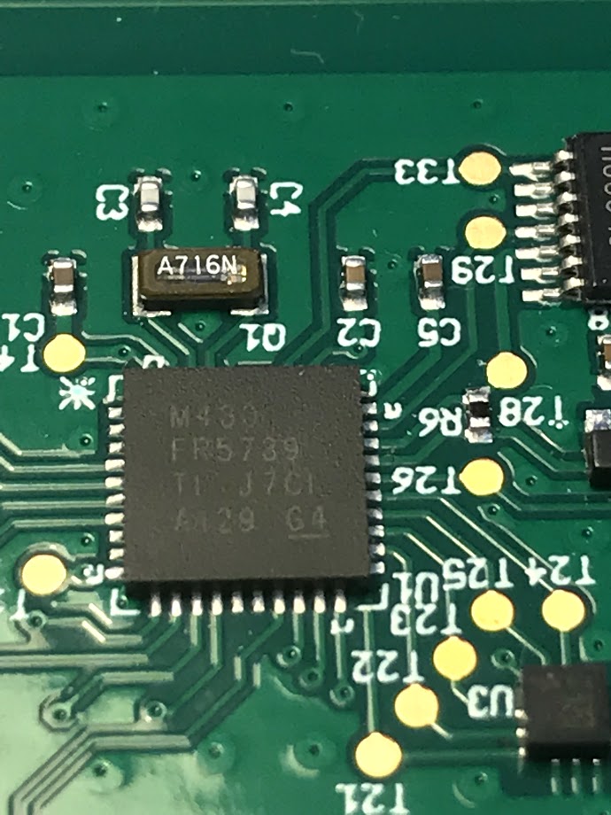
Part Number: MSP430FR5739
Other Parts Discussed in Thread: MSP430FR5730, MSP430FR5994
Hi,
we have a custom board where a mems accelerator is connected via SPI to the MSP430FR5739. With the latest production of 1500 boards (another 1500 are waiting for production) we figured out a current consumtion with a high variation starting from 0.9 uA, which is as expected, up to 1mA, which is far above expected numbers. All boards should enter LPM4.5 and having somthing arount 1uA of current consumtion. With previous productions of the board (4000 boards in total within the last 3 years) we had no problems with current consumtion.
I've done a firmware based on a LPM4 example which will reproduce the problem (see code below). When i put the red marked code line in comments, everything is fine and the current consumtion is 1.2uA. When uncommented, the consumtion is increased (fixed to a certain value for a certain board). With borads from previous productions there is no difference (MSP430fr5739 Revision H and J), either versions (commented and uncommented) are working fine. Ive measured the current consumtion on the Vcc input with different multimeters showing the same numbers.
Port settings are as port functions in use, unconnected ports are set as output low value. The marking on the MSP430 chips of the new board are: MSP430FR5739 TI J7C1 A129 G4
//******************************************************************************
// MSP430FR57xx Demo - Enters LPM4
//
// Description: Device enters LPM4
//
// MSP430FR57x
// ---------------
// /|\| |
// | | |
// --|RST |
// | |
// | |
// | P1.0 |---> Disconnect JP3 for power meas.
//
// Priya Thanigai
// Texas Instruments Inc.
// August 2010
// Built with IAR Embedded Workbench Version: 5.10 & Code Composer Studio V4.0
//******************************************************************************
#include "msp430fr5739.h"
/*+++++++++++++++++++++++++++++++++++++++++++++++++++++++++++++++++++++++++*/
/** @fn SPIInit
*
* @brief Initialize the SPI hardware.
*
* @param none
*
* @return none
*+++++++++++++++++++++++++++++++++++++++++++++++++++++++++++++++++++++++++++
*/
void SPIInit(void)
{
/* configure and init SPI */
UCA0CTLW0 = UCSWRST; /* Put state machine in reset */
UCA0CTLW0 |= UCCKPH | UCMSB | UCMST | UCSYNC;
UCA0CTLW0 |= UCSSEL_2; /* SMCLK = 1MHz */
UCA0BRW = 1; /* use 1MHz SMCLK --> 1MHz */
/* turn on state machine when needed! */
UCA0CTLW0 &= ~UCSWRST; /* Initialize USCI state machine */
}
void main(void)
{
WDTCTL = WDTPW + WDTHOLD; // Stop WDT
PADIR = 0x7C1F;
PAOUT = 0x0400; /* set LIS2DH Chip selelct to high state */
PAREN = 0x8000;
PASEL1 = 0x03E0;
PBDIR = 0x038F; /* Enable NFC_WAKEUP_BIT as INPUT */
PBOUT = 0x0040;
PBREN = 0x0040;
PJDIR = 0xFF;
PJOUT = 0x10;
PJSEL0 = 0x10;
/* configure Reset pin, enable pullup/pulldown resitor end enable Pullup */
SFRRPCR = SYSRSTRE + SYSRSTUP;
CSCTL0_H = 0xA5;
CSCTL1 |= DCOFSEL0 + DCOFSEL1; // Set max. DCO setting
CSCTL2 = SELA_0 + SELS_3 + SELM_3; // set ACLK = LFXT1; MCLK = DCO
CSCTL3 = DIVA_0 + DIVS_3 + DIVM_0; // set all dividers
if (PM5CTL0 & LOCKLPM5)
{
PMMCTL0_H = PMMPW_H; /* open PMM */
PM5CTL0 &= ~LOCKLPM5; /* Clear LOCKLPM5 and enable ports */
PMMCTL0_H = 0x00; /* close PMM */
}
CSCTL4 = XT2OFF;
do
{
CSCTL5 &= ~XT1OFFG;
// Clear XT1 fault flag
SFRIFG1 &= ~OFIFG;
}while (SFRIFG1&OFIFG); // Test oscillator fault flag
REFCTL0 |= REFTCOFF;
REFCTL0 &= ~REFON;
SPIInit();
/* do some spi read and/or write */
/* disable SPI */
UCA0CTLW0 |= UCSWRST; /* Put state machine in reset */
/* change port setting */
CSCTL0_H = CSKEY_H;
CSCTL4 |= XT1OFF; /* stop LF Oscillator */
#if 1
/* enter LPM4.5 */
PMMCTL0_H = PMMPW_H; /* open PMM */
PMMCTL0_L |= PMMREGOFF; /* set Flag to enter LPM4.5 with LPM4 request */
PMMCTL0_L &= ~(SVSHE + SVSLE);
#endif
__bis_SR_register(LPM4_bits + GIE);
}