This thread has been locked.
If you have a related question, please click the "Ask a related question" button in the top right corner. The newly created question will be automatically linked to this question.
Tool/software: Code Composer Studio
Hey everyone!
Hello,
I am working with a motor driver evaluation module (DRV8837EVM) where I have replaced the existing MCU (G2131) with an FR2111. The idea is to get everything functioning the way it was with the G2131 but with the FR2111.
The hardware is set up, I have identified where the PWM is coming from and have adjusted the duty cycle accordingly, and the DC motor runs as intended. The idea is to enable this device to be able to toggle the direction of the motor from clockwise to counter-clockwise and vice versa. Currently, I am able to do this by connecting the PWM signal to test point IN1 to have it turn counter-clockwise and to IN2 to have it turn clockwise.
The goal is to have it connected to a GPIO so that I may be able to toggle this action. Is my code optimal in achieving this? Can my current method of changing the direction of the motor be improved on?
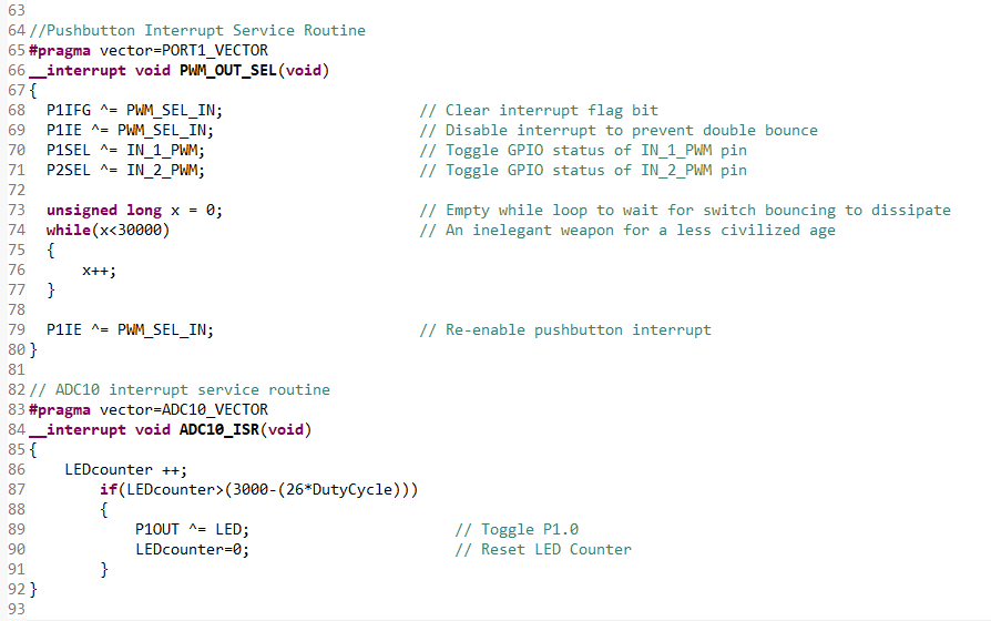
Below is the code currently on the MSP430G2131 regarding this operation:
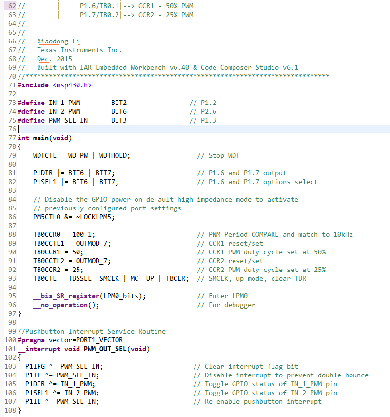
Below you'll see the code currently on my MSP430FR2111:
Any help is greatly appreciated. Thank you!
Hey Gary,
It builds without any errors. Below you will find the code for both:
MSP430G2131 Code:
#include "msp430g2131.h" #define LED BIT1 // P1.1 #define IN_1_PWM BIT2 // P1.2 #define IN_2_PWM BIT6 // P2.6 #define ADC_VREF BIT4 // P1.4 #define PWM_SEL_IN BIT3 // P1.3 volatile unsigned int LEDcounter=0; // Initialize LED timing counter volatile unsigned int DutyCycle; int main(void) { WDTCTL = WDTPW + WDTHOLD; // Stop watchdog timer //Configure Port Directions and Peripherals P1DIR |= IN_1_PWM | LED; // Set Port 1 GPIO to output on P1.1 and P1.2 P2DIR = IN_2_PWM; // Set Port 2 GPIO to output on P2.6 only P1OUT = LED; // Set P1OUT to a known state P2OUT &= 0X00; // Set P2OUT to a known state P1SEL = IN_1_PWM; // Select secondary functionality on P1.2, tying it to TA1 P2SEL &= ~IN_2_PWM; // Make sure P2.6 peripheral functionality is disabled BCSCTL3 = LFXT1S_3; // Register value that must be set to allow TAI functionality on XIN pin // Configure Timer A Capture/Compare Register to Generate 10KHz PWM with adjustable duty cycle CCR0 = 100 - 1; // Set PWM frequency to ~10KHz CCTL1 = OUTMOD_7; // CCR1 in set/reset mode CCR1 = 50; // Set duty cycle to 50% TACTL = TASSEL_2 + MC_1; // SCLK source, up mode // Configure Port 1 Pushbutton Interrupt P1REN = PWM_SEL_IN; // Enable Pullup/pulldown Resistor on P1.3 P1OUT &= ~PWM_SEL_IN; // Set resistor to pulldown on P1.3, P1IFG = 0x00; // Clear all interrupt flags on port 1 P1IE = PWM_SEL_IN; // Enable interrupts on Port 1 pushbutton pin P1IES &= ~BIT3; // Set the interrupt to trigger on a low-to-high transition on port 1.3 // Configure ADC10 to supply reference voltage and read value of voltage divider on P1.0 ADC10CTL0 |= REFON + REF2_5V + REFOUT; // Set ADC reference voltage on, at 2.5V, and output on pins with Vref+ functionality ADC10CTL0 |= SREF_1 + ADC10SHT_2 + ADC10ON + ADC10IE; // VR+ = VREF+, VR- =AVSS, 16x sample and conversion, enable ADC and ADC interrupt ADC10AE0 |= INCH_0; // Enable ADC input on A0 // Main Body of Code _BIS_SR(GIE); // Global interrupt enable for (;;) { ADC10CTL0 |= ENC + ADC10SC; // Sampling and conversion start DutyCycle = ((ADC10MEM*20)/0x3FF)*5; CCR1 = DutyCycle; } } //Pushbutton Interrupt Service Routine #pragma vector=PORT1_VECTOR __interrupt void PWM_OUT_SEL(void) { P1IFG ^= PWM_SEL_IN; // Clear interrupt flag bit P1IE ^= PWM_SEL_IN; // Disable interrupt to prevent double bounce P1SEL ^= IN_1_PWM; // Toggle GPIO status of IN_1_PWM pin P2SEL ^= IN_2_PWM; // Toggle GPIO status of IN_2_PWM pin unsigned long x = 0; // Empty while loop to wait for switch bouncing to dissipate while(x<30000) // An inelegant weapon for a less civilized age { x++; } P1IE ^= PWM_SEL_IN; // Re-enable pushbutton interrupt } // ADC10 interrupt service routine #pragma vector=ADC10_VECTOR __interrupt void ADC10_ISR(void) { LEDcounter ++; if(LEDcounter>(3000-(26*DutyCycle))) { P1OUT ^= LED; // Toggle P1.0 LEDcounter=0; // Reset LED Counter } }
MSP430FR2111 code:
#include <msp430.h> #define IN_1_PWM BIT2 // P1.2 #define IN_2_PWM BIT6 // P2.6 #define PWM_SEL_IN BIT3 // P1.3 int main(void) { WDTCTL = WDTPW | WDTHOLD; // Stop WDT P1DIR |= BIT6 | BIT7; // P1.6 and P1.7 output P1SEL1 |= BIT6 | BIT7; // P1.6 and P1.7 options select // Disable the GPIO power-on default high-impedance mode to activate // previously configured port settings PM5CTL0 &= ~LOCKLPM5; TB0CCR0 = 100-1; // PWM Period COMPARE and match to 10kHz TB0CCTL1 = OUTMOD_7; // CCR1 reset/set TB0CCR1 = 50; // CCR1 PWM duty cycle set at 50% TB0CCTL2 = OUTMOD_7; // CCR2 reset/set TB0CCR2 = 25; // CCR2 PWM duty cycle set at 25% TB0CTL = TBSSEL__SMCLK | MC__UP | TBCLR; // SMCLK, up mode, clear TBR __bis_SR_register(LPM0_bits); // Enter LPM0 __no_operation(); // For debugger } //Pushbutton Interrupt Service Routine #pragma vector=PORT1_VECTOR __interrupt void PWM_OUT_SEL(void) { P1IFG ^= PWM_SEL_IN; // Clear interrupt flag bit P1IE ^= PWM_SEL_IN; // Disable interrupt to prevent double bounce P1DIR ^= IN_1_PWM; // Toggle GPIO status of IN_1_PWM pin P1SEL1 ^= IN_2_PWM; // Toggle GPIO status of IN_2_PWM pin P1IE ^= PWM_SEL_IN; // Re-enable pushbutton interrupt }
**Attention** This is a public forum