This thread has been locked.

If you have a related question, please click the "Ask a related question" button in the top right corner. The newly created question will be automatically linked to this question.

MSP430F2274: Failure when connecting to UART

Part Number: MSP430F2274
Other Parts Discussed in Thread: MSP-FET, MSP-TS430DA38

Been trying to connect my device and utilize the UART connection to see the output from PuTTY, but keep getting a failure. The code is an example from the online resources guide, but when I try to load the project I get two different error messages. One is that the it cannot connect to COM65 at Baud 9600, which does not exist after looking at the connections on the computer's control panel. Another issue is after trying to configure the targetConfigs file to set up COM4 as the UART connection, which returns a "Load program error" with the following messages:

ComPort: Trouble Writing Memory Block at 0x8000 on Page 0 of Length 0x156: Read timed out
ComPort: File Loader: Verification failed: Target failed to write 0x8000
ComPort: GEL: File: C:\Users\sean.kramer\workspace_v8\printf_msp430\Debug\printf_msp430.out: Load failed.

Is there a reason why there is no connection, or a method of fixing this? I have searched online for similar issues and their fixes did not work for this problem. Thank you.

  • Hi Sean,

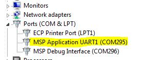
    Typically, all you need to do is open your device manager to view the available COM ports.  I don't know how you are connecting your MSP430F2274 to your PC's serial port, but I'll assume you are using either a Launchpad or MSPFET programmer, in which case the device manager should appear something like the following:

    You shouldn't have to make any changes to your target configuration in CCS, but you will need to setup PUTTY to use the "MSP Application UART" com port that shows up in your device manager.

  • yes, I checked that and found the device connect to COM4, but on CCS it looks for COM65. Changing that UART connection from COM65 to COM4 results in the error messages I presented above.

  • Sean Kramer said:
    Been trying to connect my device and utilize the UART connection to see the output from PuTTY

    What is your device? A schematic snippet would also help.

    Sean Kramer said:
    Another issue is after trying to configure the targetConfigs file to set up COM4 as the UART connection, which returns a "Load program error" with the following messages

    I'm not sure why you're doing this. Most likely, the targetConfigs file is configuring the debugger connection and not the application connection. I suspect that you're trying to program your device over the application connection rather than the debugger connection. If you're using the MSP-FET, you'll have both connections. Again, it'd be helpful to know what debugger you're using, but I don't see it mentioned.

    Regards,

    James

    MSP Customer Applications

  • A snippet of the UART schematic? The device is the MSP430F2274. When creating a new CCS project in CCSv8, there is an option for the connection, which I assumed was the ability to connect to the UART, I will create a new project and not select the UART connection and see what happens.
  • Sean Kramer said:
    A snippet of the UART schematic?

    Yes, the schematic is helpful for identifying things like wrong USCI ports, swapped TX/RX pins, etc.

    Sean Kramer said:
    The device is the MSP430F2274.

    Understood. You included the part number in your first post, but it doesn't tell us if you're using the device on a custom board, our target socket board, or one of our EVMs. The more we know, the more we can help.

    Sean Kramer said:
    When creating a new CCS project in CCSv8, there is an option for the connection, which I assumed was the ability to connect to the UART, I will create a new project and not select the UART connection and see what happens.

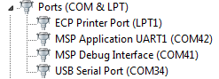
    Do you mean the "Connection" drop-down menu shown below? Keep the connection as Default, TI MSP430 USB1. Then, look in the Device Manager under Ports to find the COM port to select in Putty.

    For me, I have a MSP-FET connected to my PC. Under Device Manager, I see two COM ports: MSP Application UART1 (COM42) and MSP Debug Interface (COM41). Assuming that I kept the default connection in the CCS project settings, I should be able to connect to the MSP430F2274 over UART using COM42 in Putty.

    I hope this helps.

    Regards,

    James

    MSP Customer Applications

  • here is the schematic for the UART

    Here is my code:

    #include <msp430.h>
    
    const char string1[] = { "Hello World\r\n" };
    unsigned int i;
    
    int main(void)
    {
      WDTCTL = WDTPW + WDTHOLD;                 // Stop WDT
      P1DIR = 0xFF;                             // All P1.x outputs
      P1OUT = 0;                                // All P1.x reset
      P2DIR = 0xFF;                             // All P2.x outputs
      P2OUT = 0;                                // All P2.x reset
      P3SEL = 0x30;                             // P3.4,5 = USCI_A0 TXD/RXD
      P3DIR = 0xFF;                             // All P3.x outputs
      P3OUT = 0;                                // All P3.x reset
      P4DIR = 0xFF;                             // All P4.x outputs
      P4OUT = 0;                                // All P4.x reset
      UCA0CTL1 |= UCSSEL_1;                     // CLK = ACLK
      UCA0BR0 = 0x03;                           // 32kHz/9600 = 3.41
      UCA0BR1 = 0x00;                           //
      UCA0MCTL = UCBRS1 + UCBRS0;               // Modulation UCBRSx = 3
      UCA0CTL1 &= ~UCSWRST;                     // **Initialize USCI state machine**
      IE2 |= UCA0RXIE;                          // Enable USCI_A0 RX interrupt
    
      __bis_SR_register(GIE);       // Enter LPM3 w/ int until Byte RXed
    }
    
    #if defined(__TI_COMPILER_VERSION__) || defined(__IAR_SYSTEMS_ICC__)
    #pragma vector=USCIAB0TX_VECTOR
    __interrupt void USCI0TX_ISR(void)
    #elif defined(__GNUC__)
    void __attribute__ ((interrupt(USCIAB0TX_VECTOR))) USCI0TX_ISR (void)
    #else
    #error Compiler not supported!
    #endif
    {
      UCA0TXBUF = string1[i++];                 // TX next character
    
      if (i == sizeof string1 - 1)              // TX over?
        IE2 &= ~UCA0TXIE;                       // Disable USCI_A0 TX interrupt
    }
    
    #if defined(__TI_COMPILER_VERSION__) || defined(__IAR_SYSTEMS_ICC__)
    #pragma vector=USCIAB0RX_VECTOR
    __interrupt void USCI0RX_ISR(void)
    #elif defined(__GNUC__)
    void __attribute__ ((interrupt(USCIAB0RX_VECTOR))) USCI0RX_ISR (void)
    #else
    #error Compiler not supported!
    #endif
    {
      if (UCA0RXBUF == 'u')                     // 'u' received?
      {
        i = 0;
        IE2 |= UCA0TXIE;                        // Enable USCI_A0 TX interrupt
        UCA0TXBUF = string1[i++];
      }
    }
    

    When viewing the device manger, I only see a single COM port connect, which is unlike the image your provided. I am not using a MSP-FET device though, it is connect to the computer through an USB.

  • Sean Kramer said:
    I am not using a MSP-FET device though, it is connect to the computer through an USB.

    What is this USB device? Please provide a detailed description. The CCS error in your initial post makes sense if you're trying to program the device or communicate over UART without using one of our tools, such as the MSP-FET or an eZ-FET. If you're using a generic USB-to-serial adapter, CCS doesn't need to know about it (and most likely doesn't support it), only Putty does.

    Regards,

    James

    MSP Customer Applications

  • The device I am using is the eZ430-RF2500 Development Tool. Here is an image of the device

  • Sean Kramer said:
    The device I am using is the eZ430-RF2500 Development Tool. Here is an image of the device

    Thank you! OK, things are starting to make more sense.

    There seems to be an issue with your clock or baud rate settings. Using your code on the eZ430-RF2500, I could enter the UART RX ISR, but the RX buffer had 0xFF (didn't match the keyboard input), so I suspected it's a baud rate issue. Using the code below, I got the "Hello World" to show up in Putty after I entered the "u" character.

    #include <msp430.h>
    
    const char string1[] = { "Hello World\r\n" };
    unsigned int i;
    
    int main(void)
    {
        WDTCTL = WDTPW + WDTHOLD;                 // Stop WDT
        if (CALBC1_1MHZ==0xFF)                   // If calibration constant erased
        {
          while(1);                               // do not load, trap CPU!!
        }
        DCOCTL = 0;                               // Select lowest DCOx and MODx settings
        BCSCTL1 = CALBC1_1MHZ;                    // Set DCO
        DCOCTL = CALDCO_1MHZ;
        P1DIR = 0xFF;                             // All P1.x outputs
        P1OUT = 0;                                // All P1.x reset
        P2DIR = 0xFF;                             // All P2.x outputs
        P2OUT = 0;                                // All P2.x reset
        P3SEL = 0x30;                             // P3.4,5 = USCI_A0 TXD/RXD
        P4DIR = 0xFF;                             // All P4.x outputs
        P4OUT = 0;                                // All P4.x reset
        UCA0CTL1 |= UCSSEL_2;                     // SMCLK
        UCA0BR0 = 104;                            // 1MHz 9600
        UCA0BR1 = 0;                              // 1MHz 9600
        UCA0MCTL = UCBRS0;                        // Modulation UCBRSx = 1
        UCA0CTL1 &= ~UCSWRST;                     // **Initialize USCI state machine**
        IE2 |= UCA0RXIE;                          // Enable USCI_A0 RX interrupt
    
        __bis_SR_register(GIE);
        while(1);
    }
    
    #if defined(__TI_COMPILER_VERSION__) || defined(__IAR_SYSTEMS_ICC__)
    #pragma vector=USCIAB0TX_VECTOR
    __interrupt void USCI0TX_ISR(void)
    #elif defined(__GNUC__)
    void __attribute__ ((interrupt(USCIAB0TX_VECTOR))) USCI0TX_ISR (void)
    #else
    #error Compiler not supported!
    #endif
    {
      UCA0TXBUF = string1[i++];                 // TX next character
    
      if (i == sizeof string1 - 1)              // TX over?
        IE2 &= ~UCA0TXIE;                       // Disable USCI_A0 TX interrupt
    }
    
    #if defined(__TI_COMPILER_VERSION__) || defined(__IAR_SYSTEMS_ICC__)
    #pragma vector=USCIAB0RX_VECTOR
    __interrupt void USCI0RX_ISR(void)
    #elif defined(__GNUC__)
    void __attribute__ ((interrupt(USCIAB0RX_VECTOR))) USCI0RX_ISR (void)
    #else
    #error Compiler not supported!
    #endif
    {
        _no_operation();                          // Set breakpoint here
        if (UCA0RXBUF == 'u')                     // 'u' received?
      {
        i = 0;
        IE2 |= UCA0TXIE;                        // Enable USCI_A0 TX interrupt
        UCA0TXBUF = string1[i++];
      }
    }

    I hope this helps.

    Regards,

    James

    MSP Customer Applications

  • Even when running the code example you provided (thank you btw), I cannot see anything on the PuTTY screen. nothing I input will allow "hello, world" to be presented, and I cannot see any of the characters which I input. The settings for PuTTY is serial, 9600 baud rate on COM4, 8 data bits, 1 stop bit, no parity, and no flow control.
  • Try closing CCS, unplugging the eZ430-RF2500 and plugging it back into your PC, check the COM port in Device Manager, and then launch Putty with that COM port selected with your settings mentioned above.

    Regards,

    James

    MSP Customer Applications
  • Tried that, nothing shows up when entering keyboard presses to PuTTY. I also tried to close PuTTY and open a shell command console within CCS and although it shows that the UART connect is working, nothing shows up in the console when trying interact with it, and now CCS is not responding
  • Thanks for trying that. Forgive me if this is a stupid question, but you're keeping the two boards connected together when they're plugged into the USB port, right?

    Let's assume so (the wireless piece is entirely different discussion). Next, try closing everything, CCS, Putty, etc. Disconnect/re-connect the eZ430-RF2500 to your PC. Open CCS, create a new project (keep the default connection!) with a 'main.c' file, copy my code into 'main.c', save the project, click Download and Debug to program the device and click Run, put a breakpoint at the NOP on Line 58. Now, open Device Manager, identify the MSP Application COM port, open Putty, open a terminal on that COM port, and type something on your keyboard. In CCS, see if the code halted at the no operation at Line 58. If it did, then you know it's reading your key presses. To go a level deeper, you can view the UART registers to see what's in the RX buffer. If the code does not halt at this breakpoint, then it's not reading the keyboard input.

    Regards,

    James

    MSP Customer Applications
  • Yes the two devices shown in the picture I provided are kept together during the download/debug/run process. Now performing the tasks you provided, the breakpoint is never reached. When pressing the "pause" command, the program is stuck at the while(1) loop, and this was done after opening a PuTTY terminal with the appropriate connections and trying to enter key presses.

    Also, I have noticed that in previous programs the device will not successfully run the program until I stop the debug, disconnect the device, and plug it back in. Is this common with CCS or is there a problem with the device. For example, a simple program will blink the led after an interrupt of TimerA overflowing, but this will only occur once until the device is disconnected and plugged back in.
  • Any advice to fix this issue?
  • Hello Sean,

    Using an eZ430-RF2500 with CCS v8.0.0, I can program the code that I shared earlier, open a terminal on the MSP430 Application UART COM port, type a "u", and see "Hello World" printed in the terminal. The only other thing that I think could be causing an issue here would be if you're using Windows 10 and/or USB 3.0. I'm using Windows 7. The eZ430 is a very old debugger.

    Please keep in mind that the eZ430-RF2500 is a very old tool (developed with Windows XP), and unfortunately there won't be support for it anymore. If your project doesn't require the MSP430F2274, I would encourage you to check out our newer MSP430FR2xx devices. If you can't change devices, I would strongly recommend purchasing the target development board (MSP-TS430DA38) for the MSP430F2274 and also purchasing our newest debugger, the MSP-FET.

    Migrating From the MSP430F2xx and MSP430G2xx Families to the MSP430FR4xx and MSP430FR2xx Family

    Migrating from the MSP430F2xx and MSP430G2xx Families to the MSP430FR58xx/FR59xx/68xx/69xx Family

    Unfortunately, I'm not sure how much more I can help.

    Regards,

    James

    MSP Customer Applications

  • Thank you, although this did not necessarily solve the issue, I am using Windows 10 and will relay this information to my adviser to see if we can get those tools.

**Attention** This is a public forum