This thread has been locked.

If you have a related question, please click the "Ask a related question" button in the top right corner. The newly created question will be automatically linked to this question.

CCS/MSP430G2452: MSP430 stuck after ADC repeat single channel conversion

Part Number: MSP430G2452

Tool/software: Code Composer Studio

Hi,

I'm still stuck in a loop because I cannot get a interrupt after conversion & data transfer. So my CPU never wake.

I checked GIE and ADC10IE while debugging. They are set to 1. ADC10BUSY bit is 1. ADC10IFG is  0.

Any suggestions?

Best Regards

Here is the code:

#define     ADC_CHANNELS     5  				//We will sample 5 channels, 0 to 4
unsigned int samples[ADC_CHANNELS];

int main(void)
{

  P1SEL = BIT4;			//config p1.4 as ADC input
  P1SEL2 = BIT4;

  WDTCTL = WDTPW + WDTHOLD;                 // Stop WDT

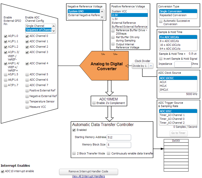
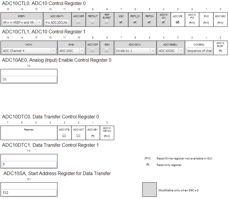
// ********** ADC init

  ADC10CTL0 = ADC10ON | SREF_1 | ADC10SHT_3 | ADC10IE | REFON | REF2_5V ;

  ADC10CTL1 = CONSEQ_1 | ADC10SSEL_2 | ADC10DIV_0 | SHS_0 | INCH_4;

  ADC10AE0 = 0x1F; // 5 channel

  ADC10DTC1 = 5;	// bloc size = 5 ADC values 16bits

  ADC10SA = (unsigned int) samples;            // Data buffer start, pointer

  ADC10CTL0 |= ENC;

  ADC10SA = (unsigned int) samples;            // Data buffer start, pointer

/****** main loop
  for (;;)
  {
    ADC10CTL0 &= ~ENC;
    while (ADC10CTL1 & ADC10BUSY);               // Wait if ADC10 core is active
    ADC10SA = (unsigned int)&(samples);            // Data buffer start, pointer
    ADC10CTL0 |= ENC + ADC10SC;             // Sampling and conversion start
    __bis_SR_register(CPUOFF + GIE);        // LPM0, ADC10_ISR will force exit
  }
}

//*******  ADC10 interrupt service routine
#if defined(__TI_COMPILER_VERSION__) || defined(__IAR_SYSTEMS_ICC__)
#pragma vector=ADC10_VECTOR
__interrupt void ADC10_ISR(void)
#elif defined(__GNUC__)
void __attribute__ ((interrupt(ADC10_VECTOR))) ADC10_ISR (void)
#else
#error Compiler not supported!
#endif
{
  __bic_SR_register_on_exit(CPUOFF);        // Clear CPUOFF bit from 0(SR)
}

  • > ADC10CTL0 = ADC10ON | SREF_1 | ADC10SHT_3 | ADC10IE | REFON | REF2_5V ;
    With MSC=0 the ADC only does one channel per trigger. [Ref SLAU144J Fig. 22-6.] Try:
    > ADC10CTL0 = ADC10ON | SREF_1 | ADC10SHT_3 | ADC10IE | REFON | REF2_5V | MSC ;
    -----------------------------------
    > ADC10CTL1 = CONSEQ_1 | ADC10SSEL_2 | ADC10DIV_0 | SHS_0 | INCH_4;
    MCLK doesn't operate in LPM0 (CPUOFF) [Ref SLAU144J Table 2-2.]. Try ADC10OSC (ADC10SSEL_0) or SMCLK (ADC10SSEL_3).

    [Edit: Fixed typo]

  • Alas, this had no effect .  I built a new program with grace for the config and kept my main loop, editing vector interruption for CPUOFF.

    Yes, ADC10OSC clock is tied to ADC10 and should be working in LPM0 (CPUOFF).

    But setting MSC will repeat conversions without trigger from AC10SC.

    I want to start conversions on demand.

    Here is some infos: 

    #define     ADC_CHANNELS     5  				//We will sample 5 channels, 0 to 4
    	unsigned int samples[ADC_CHANNELS];
    int i;
    
    int main(void)
    {
    	Grace_init();                    // Activate Grace-generated configuration
    
    	WDTCTL = WDTPW + WDTHOLD; // Set hold bit and clear others
        ADC10SA = (unsigned int)&(samples);            // Data buffer start, pointer, just to be sure
        while(1)
        {
            ADC10CTL0 &= ~ENC;
            while (ADC10CTL1 & ADC10BUSY);               // Wait if ADC10 core is active
            ADC10SA = (unsigned int)&(samples);            // Data buffer start, pointer
            ADC10CTL0 |= ENC + ADC10SC;             // Sampling and conversion start
            __bis_SR_register(CPUOFF + GIE);        // LPM0, ADC10_ISR will force exit
            i++;									// a simple counter
        }
    }
    

  • When I made the (2) changes I suggested, it had an effect -- it collected 5 samples each time around the loop, and the loop repeated, which is what I thought you intended.

    > But setting MSC will repeat conversions without trigger from AC10SC.
    > I want to start conversions on demand.

    Then I'm not quite sure what you're trying to do. You can choose [Ref SLAU144J Figure 22-6]:

    1) With MSC=1 (and CONSEQ=1), ADC10SC (once) will capture samples from the 5 channels and then stop.
    2) With MSC=0, it will still step through the channel sequence but you'll need to set ADC10SC 5 times, once for each channel.

    The interrupt will only happen after the DTC has done all 5 channels [SLAU144J sec.22.2.10].

    Your loop was written expecting behavior (1). You can write a different loop if you want behavior (2).
  • Ok, I want behaviour 1, you are fully right. I turned on MSC with Grace and.... the counter started!

    But it stopped after 7 iterations ( i==7 ). Strange...

    I went to the registers and I found ADC10SC was not set.

    So I remembered a post about a double ADC10SC command as recommended by 

    https://e2e.ti.com/support/microcontrollers/msp430/f/166/t/263756?tisearch=e2e-quicksearch&keymatch=msp430%20%20ADC10%20no%20interrupt

    Now my counter is working almost fine, but it is weird. I'm not sure of the stability.

    When I came back to my first version, it got stuck after some 50k samples when I paused the execution to see the counter.

    I was also obliged to repeat twice the initialisation of the ADC10SA during the initialisation of the ADC to get the loop working. See below.

    	  ADC10SA = (unsigned int) samples;            // Data buffer start, pointer, mandatory
    
    	  /* Software delay for REFON to settle */
    	  __delay_cycles(30000);
    
    	  /* enable ADC10 */
    	  ADC10CTL0 |= ENC;
    
         ADC10SA = (unsigned int) samples;            	// Data buffer start, pointer, mandatory again

    I noticed this happens with the Grace version when I try to slow and use divider ADC10DIV >1 with ADC10OSC. Maybe the problem comes from the clock speed, or from the debugging?... Anyway, I have enough samples to do my calibration.

     Thank you Bruce for your precious time.

    Miss you Jens.

    I added a line, and changed the MSC with the Grace config:

    #define     ADC_CHANNELS     5  					//We will sample 5 channels, 0 to 4
    	unsigned int samples[ADC_CHANNELS];
    volatile unsigned int i;
    
    int main(void)
    {
    	Grace_init();                    				// Activate Grace-generated configuration
    
    	WDTCTL = WDTPW + WDTHOLD; 						// Set hold bit and clear others
        ADC10SA = (unsigned int) samples;            	// Data buffer start, pointer, just to be sure
    
        while(1)
        {
            ADC10CTL0 &= ~ENC;
            while (ADC10CTL1 & ADC10BUSY);                  // Wait if ADC10 core is active
            ADC10SA = (unsigned int) samples;          	// Data buffer start, pointer
            ADC10CTL0 |= ENC + ADC10SC;             	// Sampling and conversion start
            ADC10CTL0 |= ADC10SC;             		// Sampling and conversion start, I tell you again! 
            __bis_SR_register(CPUOFF + GIE);        	// LPM0, ADC10_ISR will force exit
            i++;										// a simple counter
        }
    }

  • I hadn't heard of the multiple-SC thing, but that article did remind me about a race condition where the ADC completes before reaching LPM, and thus the wakeup has no effect. This is most acute using ADC10OSC, which is 5x the speed of the default MCLK.

    In this very restricted program, the window is pretty small -- unless you hit the Pause button in the debugger (the ADC doesn't stop when you do a breakpoint). The Truly Proper sequence (which actually should be mimicked for most LPMs) would be:

    > ADC10SA = (unsigned int) samples; // Data buffer start, pointer
    __disable__interrupt(); // Close window in case we get distracted by an interrupt/breakpoint
    > ADC10CTL0 |= ENC + ADC10SC; // Sampling and conversion start
    > __bis_SR_register(CPUOFF + GIE); // LPM0, ADC10_ISR will force exit
  • I tried with a different clock source ADC10SSEL_2 = MCLK. No way. I must use ADC10OSC

    I tried your solution, no way also. I must keep the double ADC10SA  solution.

    Here is my small subroutine.


    void AD_Conversion (void) { //************************ note to me: remember to discard 1st conversion ADC10CTL0 &= ~ENC; while (ADC10CTL1 & ADC10BUSY); // Wait if ADC10 core is active ADC10SA = (unsigned int) samples; // Data buffer start, pointer __disable_interrupt(); // Close window in case we get distracted by an interrupt/breakpoint ADC10CTL0 |= ENC + ADC10SC; // Sampling and conversion start ADC10CTL0 |= ADC10SC; // Sampling and conversion start, I tell you again! __bis_SR_register(CPUOFF + GIE); // LPM0, ADC10_ISR will force exit i++; // simple test counter };
  • I defer to demonstrated success.

    When I made the changes I suggested on a G2553, I didn't need to use a double SC. But I'm not going to tell you you aren't seeing what you're seeing (:-)).

**Attention** This is a public forum