This thread has been locked.

If you have a related question, please click the "Ask a related question" button in the top right corner. The newly created question will be automatically linked to this question.

TIDM-MSP430AFE253SUBMETEREVM: Connection of neutral point to GND & to 0V point of the AC/DC Converter

Part Number: TIDM-MSP430AFE253SUBMETEREVM
Other Parts Discussed in Thread: MSP430AFE253, MSP430I2041, EVM430-I2040S

Hello,

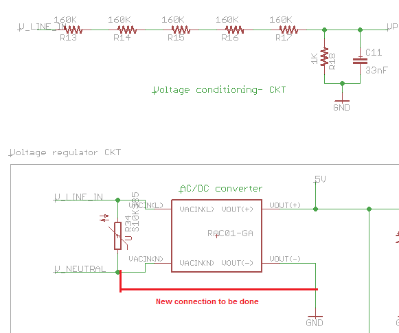
I was reviewing the TI design of the single phase energy meter using built in AC/DC converter, and as per the schematic the following is noticed:

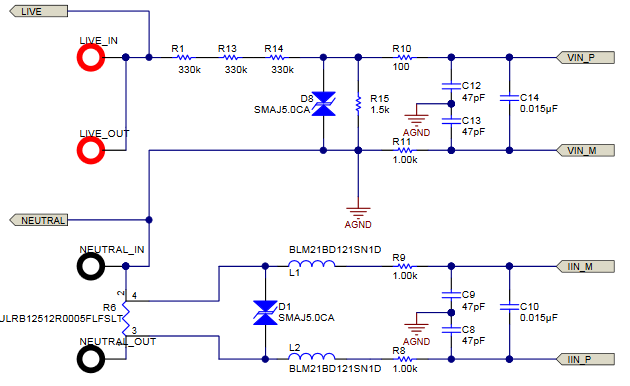
1- AC neutral point is connected to AGND

2- AGND is connected to DGND using the net Tie (NT2) as shown in the schematic.

3- 0V of the AC/DC Converter is connected to DGND using jumper J5 as shown in the schematic.

4- The above means that AC neutral point is also connected to the 0V of the AC/DC converter & to DGND.

The question is if i connect the neutral directly to the 0V of AC/DC converter is it going to have damage on the PCB? Please explain how this work?

I attached the schematic for easy reference.

Thanks,

Hishamtidr445.pdf

  • Hello Hisham,

    Neautral to GND is recommended. What you don't want to do is apply Line to GND. Does that help?
  • Hello Jace,

    Thanks for your response.

    I attached a sample from the schematic that I am preparing, the red marked wire is the wire which I am going to add between the neutral and the ground, and I am bit worried if this will blow out some components.

    Can you please have a look.

    The below GND point will be the AGND, DGND point as well.

    Thanks,

    Hisham

  • Hello Hisham,

    Moving forward, I'll be supporting this thread for Jace.

    I would highly recommend that you refer to the schematic while you construct your own design. Your proposed connection has already been done, as shown by the snippet from the schematic below. Here, Neutral is connected directly to AGND. For your AC/DC converter, I would also assume that the Neutral input is shorted internally to GND (Vout-).

    What's your maximum input voltage (e.g. 230VAC RMS)? I would be more concerned that your upper voltage divider (composed of discrete resistors R13 to R17) isn't large enough to prevent the output voltage across R18 (at maximum input voltage) from exceeding the maximum full-scale range (FSR) or even the absolute maximum input voltage to the MSP430AFE253 device.

    Also, is there a specific reason that you're using the MSP430AFE253 instead of the newer MSP430i2041? Our newly released Energy Measurement Design Center (EMDC) and software library for MSP430s with 24-bit Sigma Delta ADCs supports CCS and features an interactive GUI for quickly configuring the library, generating code, calibrating the board, and viewing results. Using one of the EMDC example projects, you can generate code, program the EVM430-i2040S, and view results in less than 5 minutes. However, the MSP430AFE253 is NOT supported by EMDC.

    Regards,

    James

    MSP Customer Applications

  • Hello James,

    Thanks for your detailed response.

    Noted for the Neutral & ground connection, it is clear now that I have to connect them.

    Regarding the resistor values the maximum input voltage is 220VAC, so the input at the Vp pin is 0.27V at 220VAC input which is within the scale.

    Regards,

    Hisham

  • Hello Hisham,

    Hisham I. said:
    Noted for the Neutral & ground connection, it is clear now that I have to connect them.

    Great!

    Hisham I. said:
    Regarding the resistor values the maximum input voltage is 220VAC, so the input at the Vp pin is 0.27V at 220VAC input which is within the scale.

    If the maximum input voltage is RMS (which it normally is), then you are correct that the max RMS input at the V(+) pin is 0.27V. However, the values for FSR are provided in peak units in the datasheet, so you'll need to convert this to non-RMS (peak) values by multiplying 0.27V to sqrt(2) which equals approximately 0.3884V peak. Thus, this input is higher than 0.250V peak for a GAIN = 2, so you'll want to use a GAIN of 1, which is preferred for better noise immunity. You could increase the lower resistance to approach the FSR at GAIN = 1 to take full advantage of the FSR (like 1.2kOhm), but 1kOhm will definitely work.

    For the i20x1 devices, the new EMDC allows users to enter the maximum voltage (RMS units), total upper resistance, and lower resistance for each voltage sensor. As you can see, the peak input voltage to the MSP430 pin is automatically calculated. Also, if you already selected and placed the MSP430i2041 before the voltage sensor, it will show the FSR for that device as the max ADC input voltage. Our intention was to make everything easier for EMDC users.

    I hope this helps.

    Regards,

    James

    MSP Customer Applications

**Attention** This is a public forum