This thread has been locked.

If you have a related question, please click the "Ask a related question" button in the top right corner. The newly created question will be automatically linked to this question.

MSP430G2433: Individual PWM output

Guru 16770 points
Part Number: MSP430G2433
Other Parts Discussed in Thread: MSP430WARE, MSP430FR2433

Hi

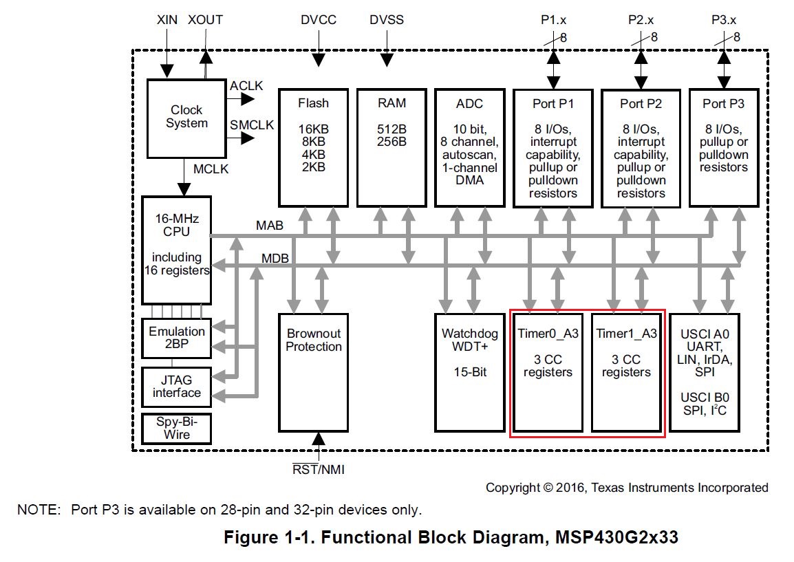
MSP430G2433 has two timers.

Is it possible to generate two PWM output with controlling them individually?

(Is it possible as many as the number of the timers?)

BestRegards

  • Hi,

    Is it possible to generate two PWM output with controlling them individually?

    Yes, you can control them individually, depending on your requirments there are different options:

    1) If you need to have two PWM output on different Timer basis, i.e. clock frequencies, you'll need to use the two different Timer modules which are on chip.

    2) In case you need the different PWM to just have different duty cycles you can use the same Timer modules but different capture/compare registers. Both Timers on MSP430G2433 have three capture compare registers.

    (Is it possible as many as the number of the timers?)

    Depending on the package you use you'd have up to six individually controllable PWM outputs (for PW28 for example) as those depend on the number of capture/compare registers rather than Timer modules. For the different scenarios, please see comment above.

    Please refer to the MSP430x2xx Family User's Guide Section 12 Timer_A for the details of PWM configuration or otherwise have a look at the code examples in MSP430Ware.

    Best regards,

    Britta

  • Hi Britta

    Thank you for your reply.

    Let me confirm the following.

    MSP430G2433 has two timer_A, timer_0 and timer_1. I think it means MSP430G2433 has two timer modules.

    So, regarding to the case of answer 1, we will need to use timer_0 and timer_1 individually.
    Regarding to the case of answer 2,
    we only have to use either timer_0 or timer_1. And one timer module can accommodate up to three PWM output.

    Is this understanding correct?

    BestRegards
  • Almost. Per Data Sheet [SLASE59B] Sec 1.4, TimerA0/A1 have 3x CCRs each, but only 2x are pinned-out (CCR0 is mediocre for PWM anyway). The other 2 timers (TimerA2/A3) have no pinned-out CCRs, so you only get 2+2+0+0 PWM channels total.
  • Hi Bruce,

    Per Data Sheet [SLASE59B]

    You are highlighting th MSP430FR2433 datasheet here, however, the correct datasheet for MSP430G2433 is SLAS734.

    As per Block diagram and pin diagrams there are only two modules present on chip TA0 and TA1.

    Also, depending on the package either 2 CCR outputs or all 3 are routed out (in case of PW28 for example).

    Nonetheless yes, you'd need CCR0 to set the output frequency, so this results in 2 possible PWM outputs per Timer module.

    Best regards,

    Britta

  • Oops. Sorry for the interruption. I'll go get my other glasses now.
  • No worries Bruce! Actually thanks for making it clearer that CCR0 will of course be used for the output frequency and wouldn't count into the real number of possible PWM outputs.
    Your help and inputs on E2E are definitely highly appreciated!

    Best regards,
    Britta
  • Hi,

    as I didn't hear back from you in a while I assume that your issue has been solved.
    Please go ahead and verify the given answer to also help other users that might run into the same issue.

    Note that I'll go ahead and close this thread in the next couple of days if I don't hear back from you. Replying to the thread will re-open it if necessary at some point.

    Best regards,
    Britta
  • Hi

    Sorry for late reply.

    I appreciate your support.

    I will open other thread if additional question has come up.

    BestRegards

**Attention** This is a public forum