- Ask a related questionWhat is a related question?A related question is a question created from another question. When the related question is created, it will be automatically linked to the original question.
Tool/software: Code Composer Studio
Hi !
I'm use CCS 8.1.
MSP430FR5972 do not cohfiguring ;-((
I need Clock System Setup:
1) Set DCO setting for 8MHz
2) ACLK == from LFMODCLK and additional divide /2
my code is:
...
 PM5CTL0 &= ~LOCKLPM5;           // Disable the GPIO power-on default high-impedance mode
                                 // to activate previously configured port settings
// Clock System Setup
 CSCTL0_H = CSKEY >> 8;                    // Unlock CS registers

 CSCTL1 &= ~DCORSEL;                       // DCO range select. Set DCO setting for 8MHz
 CSCTL1 !=  DCOFSEL_6;                     // Set DCO setting for 8MHz

 CSCTL2 != SELA__LFMODCLK;        // 010b = LFMODCLK  (ACLK == MODOSC/128)
 CSCTL2 != SELS__DCOCLK;          // 011b = DCOCLK
 CSCTL2 != SELM__DCOCLK;          // 011b = DCOCLK

 CSCTL3 != DIVA__2;          // ACLK source divider. Divides the frequency of the ACLK clock source. 001b = /2
 CSCTL3 &= ~DIVS__1;      // SMCLK source divider. Divides the frequency of the SMCLK clock source. 000b = /1
 CSCTL3 &= ~DIVM__1;      // MCLK source divider. Divides the frequency of the MCLK clock source. 000b = /1

 CSCTL4 != HFXTOFF;      // 1b = HFXT is off if it is not used as a source for ACLK, MCLK, or SMCLK
 CSCTL4 &= ~VLOOFF;      // VLO off. This bit turns off the VLO. 0b = VLO is on
 CSCTL4 &= ~SMCLKOFF;    // SMCLK off. This bit turns off the SMCLK. 0b = SMCLK on
 CSCTL4 != LFXTOFF;      // 1b = LFXT is off if it is not used as a source for ACLK, MCLK, or SMCLK

 // CSCTL5 ???
 // CSCTL6 ???

 CSCTL0_H = 0;
...
is it correct ?
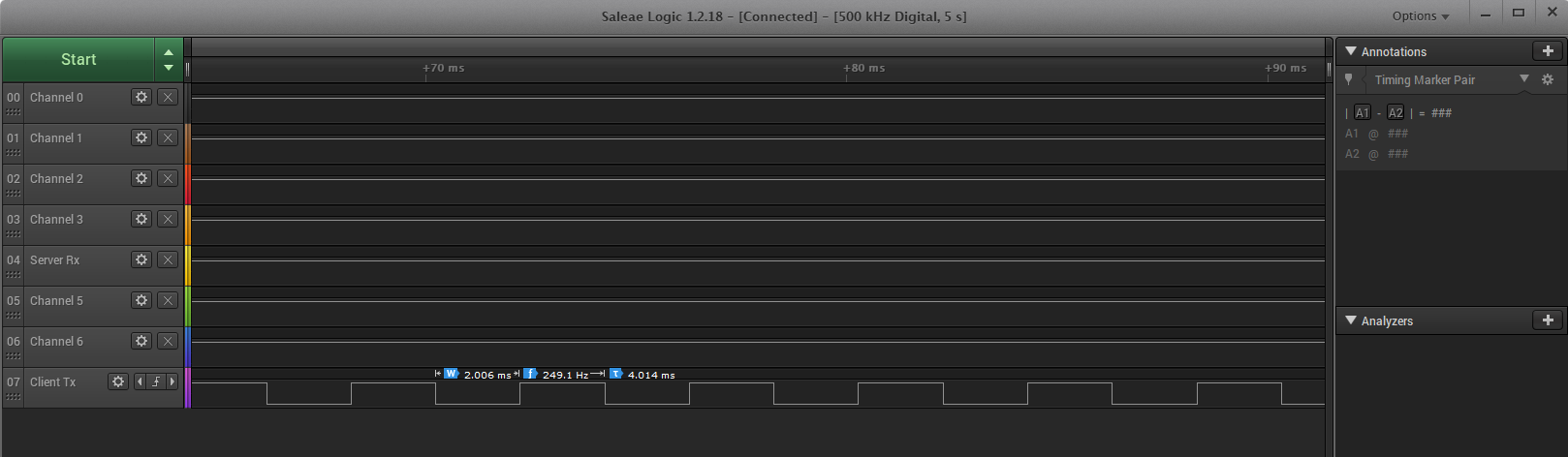
I can not get to work Timer2 :-((
I think that the problem is the wrong tuning of all frequencies...
code is:
....
//  Start init Timer2_A0 --------------


TA2CTL = TASSEL__SMCLK;       // Timer_A clock source select 00b = TAxCLK  01b = ACLK 10b = SMCLK
//TA2CTL != TASSEL_2;            // Timer_A clock source select 00b = TAxCLK  01b = ACLK 10b = SMCLK
TA2CTL &= ~ID__1;               // Timer A input divider: 0 = /1 , 1 = /2 , 2 - /4 , 3 - /8
TA2CTL != MC__UP;              // Timer A mode control: 1 - Up to CCR0
TA2CTL != TAIFG;               // Timer_A interrupt flag 0b = No interrupt pending
TA2CTL != TAIE;                // Timer_A interrupt enable. This bit enables the TAIFG interrupt request. 0b = Interrupt disabled 1b = Interrupt enabled

TA2CCTL0 &= ~CAP;              // Capture mode 0b = Compare mode 1b = Capture mode
TA2CCTL0 &= ~OUTMOD_0;          // PWM output mode: 0 */
//TA2CCTL0 != OUTMOD_1;          // PWM output mode: 1 - set */
//TA2CCTL0 &= ~COV;
//TA2CCTL0 &= ~CCIFG;
TA2CCTL0 |= COV;
TA2CCTL0 |= CCIFG;

//TA2EX0 &= ~TAIDEX_0;         // Timer_A Input divider expansion : /1

TA2CCTL0 != CCIE;     // Capture/compare interrupt enable. This bit enables the interrupt request of the corresponding CCIFG flag. 0b = Interrupt disabled 1b = Interrupt enabled
//TA2CCTL0 &= ~CCIE;  // Capture/compare interrupt enable. 0b = Interrupt disabled

TA2CCR0 = 16000 - 1;   //  500 interrupts per 1 second

//  End init Timer2_A0,  -------------------------------------------
....
is it correct ?


**Attention** This is a public forum