This thread has been locked.

If you have a related question, please click the "Ask a related question" button in the top right corner. The newly created question will be automatically linked to this question.

MSP430F449: synchronization error BSL

Part Number: MSP430F449
Other Parts Discussed in Thread: MSP-FET, MSP430G2231

Hi!

I have some device with microcontroller MSP430F449 and programmer MSP430-BSL-USB (<a href="aliexpress.com/.../2038551092.html">Here it is</a>). Manufacturer recommended for programming "Free MSP430 Programming Utility v.1.6.1014". The problem is that this software displays "synchronization error". Tell me something.

  • Hi Sergei,

    if I understood correctly you have some issues with the MSP430-BSL-USB programmer by Electronicfans. I'd suggest for you to get in contact with the supplier directly as I don't have details on their device.

    Nonetheless I'd suggest for you to also check out the MSP BSL solutions provided by Texas Instruments and we can defintely help you to get started with those.

    Please let me know in case there are any questions on the MSP BSL.

    Thanks and best regards,

    Britta

  • OK! Thank you.

    But that this http://www.ti.com/tool/mspbsl I did not understand! There is an archive with some files. What should I do with them?

  • I've got one more question: if I buy such a programmer olimex.com/.../ I can fully read and write code with MSP430F449? And if the fuse is turned off, I can write code into it?
  • Sergei Huiva said:
    I've got one more question: if I buy such a programmer olimex.com/.../ I can fully read and write code with MSP430F449? And if the fuse is turned off, I can write code into it?

    I'm not sure the Rocket will work well with the F449.  My understanding is that the Rocket is intended for parts that are programmed with BSL-Scripter (the F5xx and F6xx parts), but your F449 is programmed with BSLDEMO.  This wiki entry suggests BSLDEMO does not directly support the Rocket:

    http://processors.wiki.ti.com/images/tmp/f1391570252-215069158.html

    While options are presented there to make it work by jumping through hoops, it seems to me that the Rocket may not be the ideal solution.  TI people reading this will see that table 1 of SLAU319 does show the Rocket as being appropriate hardware for programming these parts with BSLDEMO.  I would question that unless a big footnote is added.  But perhaps I misunderstand what the Rocket does.

    Sergei, does the documentation for the programmer you have say it is only for use with BSL-Scripter, or only for F5xx and F6xx parts?  If not, you might try running BSLDEMO with it to see if that works.

  • OK! What do programmer i need to use?
  • Hi George,

    you've made a good catch here. We're updating our documentation (SLAU319), as the Rocket is not supported on F4xx devices. We need to remove it, thank you for highlighting it!
    Also, we'll remove the wiki page you've hightlighted above, as this is no the supported way, again many thanks for making us aware that this is still up.

    Best regards,
    Britta
  • Sergei,

    We encourage you to use a USB to UART bridge with  BSLDEMO code.

    Please refer to the following thread as it contains a link to BSL Scriptor and also some best practices to get started.

    I hope this will help you.

    Thanks and best regards,

    Britta

  • Britta Ruelander said:
    Hi George,

    you've made a good catch here. We're updating our documentation (SLAU319), as the Rocket is not supported on F4xx devices. We need to remove it, thank you for highlighting it!
    Also, we'll remove the wiki page you've hightlighted above, as this is no the supported way, again many thanks for making us aware that this is still up.

    Best regards,
    Britta

    Britta, I understand that you want good information out there, but I would have suggested the opposite approach - adding a footnote in 319, and leaving the wiki entry as is.  Remember that the Rocket *can* be used with these parts if you jump into BSL from the application, which continues to be an approved practice.  The real problem is that TI doesn't have a low-cost device to program these parts, and when people try to use an FTDI or other typical USB-to-serial adapter, they find that BSLDEMO doesn't work with them because of polarity issues on DTR and RTS.  So you end up referring people like Sergei to my version of BSLDEMO on Github, which solves the polarity problems, but isn't exactly signed TI-source software..  I take it back.  You do have the low-cost option presented in SLAA535 - a G2 Launchdpad and the G2452 that comes with it, but the user has to program his own interface device.  So again, I would hope that some version of the wiki entry could be left in place, and a footnote added to the Rocket checkmark in 319, at least until such time as the official version of BSLDEMO allows individual polarity control of DTR and RTS.

  • Sergei Huiva said:

    OK! What do programmer i need to use?

    TI offers the MSP-FET device, but it costs over $100.  I believe the only low-cost option offered by TI is presented in:

    http://www.ti.com/lit/an/slaa535a/slaa535a.pdf

    and the ZIP file which accompanies it.

    That PDF uses an MSP430G2 Launchpad (about $10) with an MSP430G2231 installed on it as the interface device.  You have to flash software from the ZIP file to the G2231. Using that setup, the version of BSLDEMO included in the BSL-Scripter zip should work.  I should say that I have not actually tested this 535 method, but I believe others have done so successfully.

    The alternative used by Tan in the thread Britta referred you to was to use an FTDI USB-to-serial adapter. I believe Tan used a cable with the adapter built in, but adapter modules are widely available on Ebay for about $2.  You just need one that provides both DTR and RTS outputs, and is 3.3V.  Also, other brands, like Silabs' CP2102, could be used, but in any case you will need to install the driver for the one you select.  But with this option I believe you will need to use my version of BSLDEMO to get the correct polarity for the DTR and RTS lines.  I believe for the F449 you would need to use both the -i and -j options.

    https://github.com/gbhug5a/MSP430-BSL/tree/master/BSLDEMO-2.01c

  • Hi George,

    thanks for the feedback. Let me take this back to our experts for the programming tools so that they decide on the best way to support customers on those issues. We'll definitely take this remarks into account and might need to update our documentation and maybe code examples accordingly.

    Thanks and best regards,
    Britta
  • Britta Ruelander said:
    Hi George,

    thanks for the feedback. Let me take this back to our experts for the programming tools so that they decide on the best way to support customers on those issues. We'll definitely take this remarks into account and might need to update our documentation and maybe code examples accordingly.

    Thanks and best regards,
    Britta

    Just to make you familiar with the history of the DTR/RTS polarity problem when using third party USB-to-serial adapters (FT232, CP2102, CH340, etc.), I requested an option be added to BSLDEMO to allow polarity control of DTR so those adapters would work.  In the version of BSLDEMO included in Scripter v3.3.0, an -i option was added, but it inverted BOTH lines, which just transferred the problem to the other line.  Just a misunderstanding about what was needed, probably my fault. Then in the current Scripter 3.4.0 ZIP, that option was removed, so we're back to the v3.2.1 state, with no polarity options.

    DTR needs to be inverted in all cases to work with the third party adapters.  RTS is currently correct for MSP430 parts with Test pins, but needs to be inverted for those with TCK pins.  However, to keep from breaking all the existing devices that currently do work with BSLDEMO, those inversions need to be added as non-default options.  In my recompile of the v3.2.1 version, I added -i to invert DTR and -j to invert RTS.  So all possible polarity combinations of those lines are possible.

    My modified source is included in my Github repo, and of course TI is welcome to use anything there that might be useful.  All of my source code changes are preceded by "/*  Change by GH */".  I assume TI doesn't typically feel compelled to support use of third party devices like these adapters, but the closest thing TI has to a low-cost BSL programming device for all the BSLDEMO devices is the one shown in SLAA535.  The Rocket can be used, but it doesn't support the signalling pattern on /Reset and Test when used with BSLDEMO.  Of course MSP-FET can be used, but it's ten times the cost., whereas the third-party adapters are a couple bucks.  In fact, the whole point of my Github repo was embedding these adapters in MSP430 circuits, so only a USB cable would be needed to flash new firmware.

    If TI does decide to implement the polarity control, I have a couple other changes to offer in the "while you're at it" category, but won't bother you with those now.

    You would also need to think about what changes to make to Table 1 of SLAU319 - -perhaps an additional line under Hardware for "third-parry adapters", with a checkmark for that one column only.

  • Hi George,

    again many thanks. As said, I've highlighted this to the right group inside TI to take into account when making changes to SLAU319. As of now I unfortunately don't have any concrete feedback yet with regards on their next actions and timelines.

    Meanwhile I'll go ahead and close this thread as it seems you've answered Sergeis question and he can move on.

    We appreciate your feedback and will take it into account for any improvements we plan with reggards to BSLDEMO.

    Best regards,
    Britta
  • Good morning, Britta and George!

    Thank you very much for your help. You provided a lot of information. Concerning MSP-FET, the problem is not even in value but in the fact that I can not buy it in Ukraine. All I could buy is the programmer that I wrote earlier. I would like the products TI to have Russian-language support. 

    Thanks again to all!

  • Sergei Huiva said:

    Good morning, Britta and George!

    Thank you very much for your help. You provided a lot of information. Concerning MSP-FET, the problem is not even in value but in the fact that I can not buy it in Ukraine. All I could buy is the programmer that I wrote earlier. I would like the products TI to have Russian-language support. 

    Thanks again to all!

    Sergei, if you can buy a generic USB-to-serial module locally, I believe you can use it to flash.  Such a module would be an FT232, a CP2102 or a CH340, and you would have to download and install the correct driver for the module.  Just make sure it is a 3.3V module, not 5V.  Then I  think my version of BSLDEMO would work with the module.

  • Thank you, George!

    The module that I have is built on a chip CH340T. Installed drivers, checked for 3.3 v.I already downloaded your version of BSLDEMO, thank you very much! But I did not fully understand how it works. Where can I find this information? Can I read data from the microcontroller without knowing the password? Can I count on your help with my project? If I have any questions, how can I contact you?

  • Sergei Huiva said:

    Thank you, George!

    The module that I have is built on a chip CH340T. Installed drivers, checked for 3.3 v.I already downloaded your version of BSLDEMO, thank you very much! But I did not fully understand how it works. Where can I find this information? Can I read data from the microcontroller without knowing the password? Can I count on your help with my project? If I have any questions, how can I contact you?

    Sergei, I participate here as I have time, but you will need to get the TI support people to help you get things working.  SLAU319 has most of the information about BSL (see Table 19), but I don't think I've ever seen a PDF devoted to BSLDEMO.  If you run BSLDEMO with the -h option, it will show you all of the command line options.  You have to specify the COM port your CH340T occupies, but other options depend on what you want to do.  You do have to know the password to read data.  You will have to make sure the CH430T pins DTR, RTS, TxD and RxD are connected to the appropriate pins of the F449,, and I believe you will need to use both the -i and -j options in my version of BSLDEMO. Your F449 has BSL v1.6, and I don't know what happens if you provide the wrong password.  That may cause the chip to be erased, so you must be very careful.

  • OK! But after erasing, can I write down my code again in it? What it is 

    How to use it? No information...

  • Hi Sergei,

    George is correct. In case you send the wrong password a mass erase is automatically triggered.
    After that you can prorgamm your device by providing the correct password. The password will always be the 32 Bytes at address FFE0. So in case a mass erase happened the correct password will be 0xFFFF.
    The general sequence is as follows:
    - device powered up /starts
    - BSL entry sequence needs to be applied on TST/ RST pin (DTR and CTS in your case)
    - execute BSL
    - unlock BSL by sending command and password.

    To your question a while ago: No, you cannot read the data (talking about the firmware code here) without unlocking the BSL and for this you'll need the password. Therfor you actually need to know the firmware programmed to the device.

    Was that what you question was centered around? Or did I miss something here.

    Best regards,
    Britta
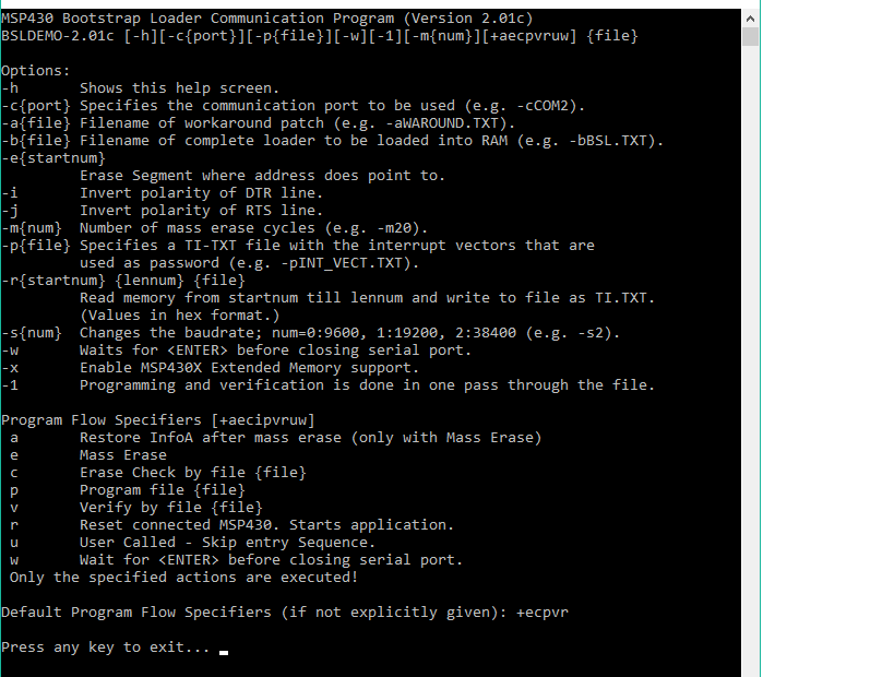
  • Sergei, BSLDEMO is a Windows console (command line) program. Usage is shown on the second line of your quote above.

    Put your password file and your new firmware file in the same folder with BSLDEMO, then Start/Run/CMD and navigate to that folder (may get to the command prompt differently on Windows 10).  If you have the CH driver installed on COM9, for example, then you would connect everything, and type something like this on the command line:

    BSLDEMO-2.01c.exe -cCOM9 -i -j -pPASSWORD.TXT -1 +ecpv FIRMWARE.TXT

    Both TXT files are in Ti-TXT format.  I'm guessing at  the i/j options, but some combination of those two should work.

    The connections from the CH to the chip would be DTR to /Reset, RTS to TCK, Tx to Rx (P1.1), Rx to Tx (P1.0), and of course ground to ground.  You may also need to connect the CH 3.3V output to the F449 VCC pin if the F449 doesn't have it's own power.

  • Thank you, George!
    You as always gave the exact answer to my question.
  • Hi, Britta!
    I think that the TI company should somehow give this information in its technical documentation. I may not be the only person who has a similar problem.
    As for the password, the question of protecting my code from extraneous people. Thank you, I heard the answer to my question.
  • Hi Sergei,

    I've taken your case back to the responsible organization inside and indicated that a documentation update may be needed.

    Thanks a lot for your input and you're right, this can definitely be important for other user's also.

    Should I go ahead and close this thread?

    Best regards,

    Britta

  • Hi Britta!

    Yes, I think the topic is revealed. But I'm interested in another question: as far as I understand the parameters -i and -j inverted signals DTR and RST, knowing the correct direction of these signals, can I invert them using hardware? Let's set the logical element NOT.

  • Hi Sergei,

    with regards to your latest question:
    Theoretically this should be possible to implement in hardware as you've described but it hasn't been tested like this by us.

    Please validate the given answers in case this thread can be solved.

    Best regards,
    Britta
  • Sergei Huiva said:

    Hi Britta!

    Yes, I think the topic is revealed. But I'm interested in another question: as far as I understand the parameters -i and -j inverted signals DTR and RST, knowing the correct direction of these signals, can I invert them using hardware? Let's set the logical element NOT.

    Sergei, my purpose in adding the -i amd -j options was to avoid the need for hardware inverters, but still allow polarity to be changed.  But you certainly can use hardware inverters instead, and that would allow you to go back to the official TI version of BSLDEMO.  The -i and -j options apply to the DTR and RTS (not RST) outputs of your USB-to-serial adapter.  Those are the lines BSLDEMO uses to initiate a BSL session, as described in SLAU319.

  • Hi George, Sergei,

    as there was no recent activity anymore on this thread I'll go ahead and close it.
    Please feel free to open a new one in case there are any more open items on your list.

    Note that I've taken your inputs back to our experts to work on improving our solution and documentation.

    Best regards,
    Britta

**Attention** This is a public forum