This thread has been locked.

If you have a related question, please click the "Ask a related question" button in the top right corner. The newly created question will be automatically linked to this question.

CCS/MSP430F5528: Low-power modes not working?

Part Number: MSP430F5528
Other Parts Discussed in Thread: MSP-FET, ENERGYTRACE, , MSP430F5529

Tool/software: Code Composer Studio

Hi,

I want to set my MSP430F5528 into LPM3, however using energyTrace (using MSP-FET) I can't see any difference at all in energy consumption between active mode and LPM3. When debugging, I can see that the debugger in CCS v7 says "MSP430: Warning: CPU is currently OFF and debugging capabilities will be limited." when putting a breakpoint by the LPM3 code. 

I also tried to set it to LPM4 to see if I would not get any respons from it anymore, but it behaves as normal and "wakes up" with the internal VLO interrupt. So I'm not sure low-power mode is working here but what could be wrong?

(Note that I am using the MSP430 that is on the TDC1000-TDC7200EVM board, if that would make any difference?)

Here is the code: 

main.c

void main(void)
{
  
  WDTCTL = WDTPW+WDTHOLD;                                                      // Stop WDT 

  // oscillator fail if LED keeps flashing after InitMCU     
  InitMCU();

  next_trigger_time = 0;


  // init 100ms interval timer (timer1)
  timer1_A0_init();

  // init timer0 A0 for programmable external osc wake up time
  // or when MSP430TIMER_TDC is true, init as capture timer to continuously run
  timer0_A0_init();


  USBPWRCTL &= ~(SLDOEN+VUSBEN); // disbale internal 3.3v and 1.8v LDOs


  while (1) // Main loop
  {

    if (next_trigger_time)
    {

      next_trigger_time = 0;

      __no_operation();
      LPM3;
      __no_operation();

    }

  }
}

interrupt service routine:

//******************************************************************************
// Timer1 A0 interrupt service routine
//------------------------------------------------------------------------------
#pragma vector=TIMER1_A0_VECTOR
__interrupt void TIMER1_A0_ISR (void)
{

    _low_power_mode_off_on_exit();

    __delay_cycles(800); // wake up time is 3.5us from LPM3
     next_trigger_time = 1;

     __no_operation();
  
}

I can't figure out what is going on here...

Kind regards,
Thibault 

  • Hi Thibault,

    Place an LPM3 instruction on line just below InitMCU(); line.

    This will cause the CPU to enter LPM3 and remain there. You can then measure the current with the energyTrace. What do you see?
  • Dennis Lehman said:
    Hi Thibault,

    Place an LPM3 instruction on line just below InitMCU(); line.

    This will cause the CPU to enter LPM3 and remain there. You can then measure the current with the energyTrace. What do you see?

    Hi ,

    Thanks for your answer! 

    I put a delay before the LPM3 instruction to clearly see when it should go to sleep. I can clearly see a decrease then as you can see in the picture below:


    This is the behaviour when the LPM3 is placed in the while loop and should wake up every 4 second as I showed in the first post. 

    So it is working at least, but I cannot see any difference in the while loop. And it is still strange that the MCU is able to wake up in LPM4.

    Thanks.

  • Next, I would use only one timer for now and set it to generate an interrupt every 100msec.
    Make your while loop is simple by just using the LPM3.
    In your timer ISR, having the software delay is fine.

    You should see a current increase in the energyTrace every 100msec.
    You should see the LPM3 currents in between.

    Can you do this?
  • Dennis Lehman said:
    Next, I would use only one timer for now and set it to generate an interrupt every 100msec.
    Make your while loop is simple by just using the LPM3.
    In your timer ISR, having the software delay is fine.

    You should see a current increase in the energyTrace every 100msec.
    You should see the LPM3 currents in between.

    Can you do this?

    Hi , sorry for the late reply!

    This is the power consumption during 1 seconds with 100ms delay and with the simple code as you described:

    I can't really see that it is working as aspected?

    Thanks in advance!

  • I was able to take your code (with a couple of modifications) and generate a timer interrupt once every second.  In the interrupt handler I have a long delay, then return back into sleep mode until the next timer interrupt.  Here is what I see.  You can see when the CPU is in LPM3, the power is around 1mW.  You can then see the interrupt handler is running the CPU in active mode with a power of 2mW.

     Here is the modified code:

    void main(void)
    {

    WDTCTL = WDTPW+WDTHOLD; // Stop WDT


    TA0CTL = TASSEL__SMCLK | ID__8 | MC__UP | TACLR ; // SMCLK / 8, up mode, clear timer
    TA0EX0 = TAIDEX_7; // (SMCLK / 8) / 8 ~ 15.625 kHz. Default SMCLK: 1MHz
    TA0CCR0 = 0x3D09; // ~1 sec
    TA0CCTL0 |= CCIE;

    _enable_interrupts();

    USBPWRCTL &= ~(SLDOEN+VUSBEN); // disbale internal 3.3v and 1.8v LDOs

    while (1) // Main loop
    {

    __no_operation();
    LPM3;
    __no_operation();

    }
    }

    //******************************************************************************
    // Timer0 A1 interrupt service routine
    //------------------------------------------------------------------------------
    #pragma vector=TIMER0_A0_VECTOR
    __interrupt void TIMER0_A0_ISR (void)
    {

    __delay_cycles(100000); // wake up time is 3.5us from LPM3

    __no_operation();

    __bic_SR_register_on_exit(LPM3_bits); // Exit active CPU

    }

    Let me know if try this code, do you see the same?

  • Hi ,

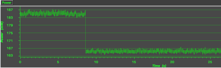
    Here is the result with your code:

    Still hard to see any difference, maybe hardware problem? I have shorted R16 and removed R15 on the TDC1000-TDC7200EVM board. I have tried both with and without the jumper JP2.

    Thanks again for your assistance!

    Kind regards,
    Thibault 

  • Hi Thibault,

    Ok, I think I see the problem. The testing I did was on an MSP430F5529 launchpad. There are no other chips or components connected to the +3.3V circuit so the only current being measured is the MSP430F5529. This is why I get 1mW in sleep mode and 2mW in active mode.

    You are using the TDC1000-TDC7200EVM, and there are several active components connected to the +3.3V circuit, so you are measuring the current going to all the devices. I seep from your plot you are getting somewhere in the neighborhood of 156mW. So basically you will never see the 1mW change in current as the MSP430F5528 goes between LPM3 and active modes.

    You mentioned you removed jumper J2. When you removed this jumper, did you connect the +3.3V from the MSPFET to J2-2 to supply power only the MSP430?
  • Hi ,

    Yeah should be the reason. It is strange that so much current is drawn when most of devices draws in the uA range. 

    Dennis Lehman said:

    You mentioned you removed jumper J2. When you removed this jumper, did you connect the +3.3V from the MSPFET to J2-2 to supply power only the MSP430?


    No I did not do that (not easy, however the CPU still works), and I think the jumper needs to be on. I removed the R15 0hm resistor as in the drawing:

  • When you remove J2, technically you are not providing 3.3V to the MSP. The MSP may still appear to operate due to current that can leak back through the IO or other pins that are connected to 3.3V.

    The bottom line here is you must properly power the MSP by having J2 installed and if you want to measure only the MSP power then you must follow the instructions I provided earlier.

**Attention** This is a public forum