Other Parts Discussed in Thread: MSP-FET
Good afternoon, we use about 10K pcs of TI MSP430F5325 on our products.
Sometimes happen we can’t program the microprocessor (about 30-40 times in a year) and we need to replace it and this is a big problem for us (expensive and leasure time).
After the replacement every thing works properly.
Let us know if there are some mistake on the electrical diagram or let us know if we can improve the programming phase.
For the program operation we use:
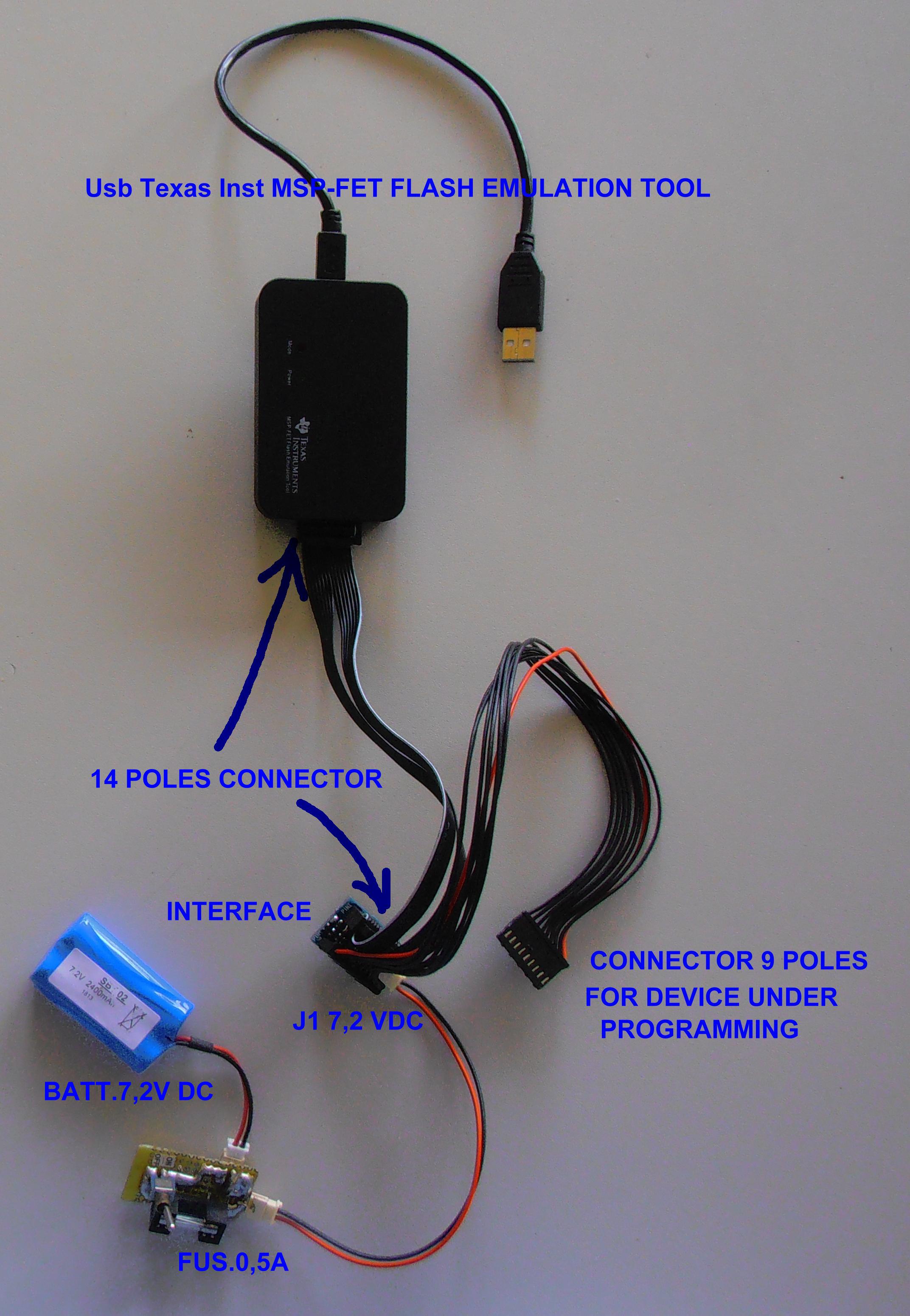
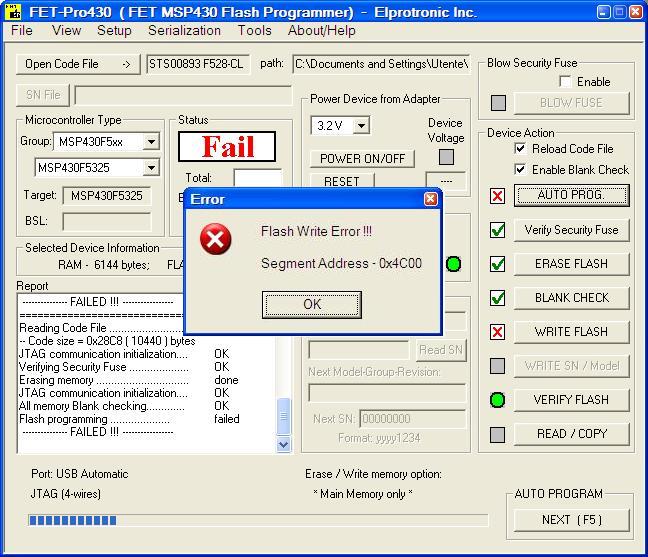
-Elprotronic sw FET-Pro430-Lite-3v41 and Usb Texas Inst MSP-FET FLASH EMULATION TOOL
In all our products we have designed a 9 poles connector for the programming operation as you can see in the electrical diagram PROGRAMMING CONNECTOR ELECTR DIAGR.pdf.
We have also designed a little pcb interface (INTERFACE ELECTRICAL DIAGRAM.pdf), useful to connect the 14 pole connector coming from MSP-FET FLASH EMULATION TOOL, the 9 poles connector of the device under programming and the power supply with a series fuse of 0.5 A. The power supply is always provided with an external 7,2 V Dc max on the J1 connector (see PROGRAMMING.JPG).
Thank you for your cooperation.
Alessandro Di Paola7043.INTERFACE ELECTRICAL DIAGRAM.pdf2845.PROGRAMMING CONNECTOR ELECTR DIAGR.pdf