


Part Number: MSP430FR2633
Tool/software: Code Composer Studio
Hi,
I have a question about the SPI timing diagram on the MSP430FR2633. As per the TI's MSP430FR2xx Family User Guide(SLAU445H–October 2014–Revised May 2018) documentation
The SPI Mode 2 which is the CKPL 1 and the CHPA 0 Mode.
For this mode, UCXCLK sequence mentioned on the diagram is contradicting with the Wikipedia definition of SPI Mode 2. Can I check if this is different for MSP430 from the traditional SPI protocol?.
Since for SPI Mode 2, The data is changed on the Rising Edge and Captured on the Falling Edge. I would expect something like below.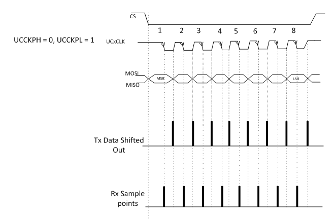
But as I understood from the diagram mentioned on the User guide, this is the inverse logic. The data is changed on the Falling Edge and Captured on the Rising Edge. Kindly correct me if I’m wrong. Can you please clarify if this is the right document for this family, or if I’m missing anything on the User guide regarding this.

Thanks in Advance.
Regards
Suresh
