This thread has been locked.

If you have a related question, please click the "Ask a related question" button in the top right corner. The newly created question will be automatically linked to this question.

MSP432P401R: parse a 5 MHz custom serial data

Part Number: MSP432P401R

Hello MSP432 champs,

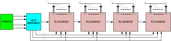
My customer is trying to drive 60-port Ethernet switch RGB LEDs using 4x TLC5955 and a MSP432, based on this TI design: 

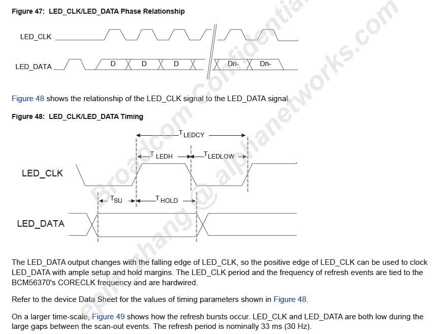
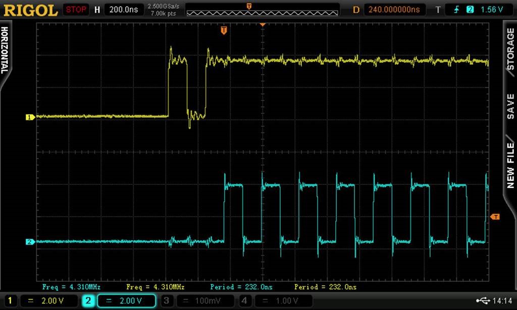
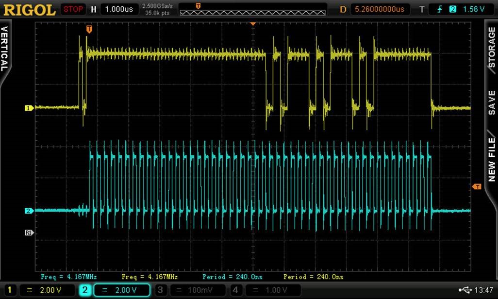
The LED data and status signal from BCM56370 is proprietary and is running at 5 MHz, as shown in Figure 47. In addition, driving 4x TLC5955 also consumes a lot of resources, currently the signal is made by driving GPIOs and timers. Therefore, I need a workable interface to capture and parse the input LED data signal from BCM56370 without consuming too much resource. Please advice! Thank you very much!

Regards,

Jo

  • I'm unable to locate a datasheet describing the proprietary protocol. Please private message me with this info.
    -Bob L.
  • Jo,

     I understand from your private message that no additional datasheet info is available.  To document that exchange, I have the following comments:

    As you’ve no doubt noticed, this is very close to SPI and configuring it for SPI will receive the data correctly. The main issue is in setting up a state machine to ensure that we are in sync when starting to receive data, and that we can read ALL the data before the next frame comes up (assuming the actual number of data bits is a multiple of 8 so that our SPI can work properly- that’s an important question to answer!.

    Some thoughts for the state machine.

    1. Starting in Idle, You can use the TimerA in Capture mode to capture the time of the clk/data. From there you could see if there was a data pulse ahead of the first Clk LH edge. (Though you have to set this up at initializtion or guarantee you are in the inter-frame gap)

    2. We can detect if we have proper framing by counting the number of Clk LH edges. (Connect the Clock to the TA1CLK pin and configure the Timer in Up-count mode). You can then check at the end of a sequence to see if you have received all the clock pulses you were expecting. (Use a Timer to trigger an interrupt for some period of time after all the bits SHOULD have been sent as a timeout).

    Let me know whether you're able to solve your issue with the above.

**Attention** This is a public forum